MT8931C
features and control functions. Signalling may be
performed by scanning the keypad and generating
appropriate messages to be packetized by the HDLC
section of the SNIC and transmitted via the D-
channel. A twelve segment, non-multiplexed LCD
display can be connected directly to the S12-S1
outputs to provide various status and call progress
indicators.
Applications
The MT8931C is useful in a wide variety of ISDN
applications.
Being used at both the Network
Termination (NT) and Terminal Equipment (TE) ends
of the line, the SNIC finds application on digital
subscriber line cards and in full featured digital
telephone sets.
It must be noted, that the pseudo-ternary line code
will tolerate line reversals within the LRx and LTx pair
between the NT and TE. However, reversal of the TE
transmit pair between two or more TEs will make the
S-interface inoperable.
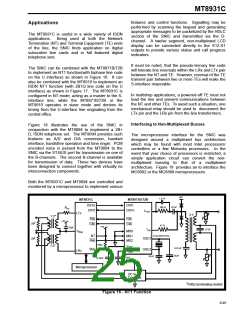
The SNIC can be combined with the MT8971B/72B
to implement an NT1 function(with biphase line code
on the U interface) as shown in Figure 16. It can
also be combined with the MT8910 to implement an
ISDN NT1 function (with 2B1Q line code on the U
interface) as shown in Figure 17. The MT8931C is
configured in NT mode, acting as a master to the S-
interface line, while the MT8971B/72B or the
MT8910 operates in slave mode and derives its
timing from the U-interface line originating from the
central office.
In multidrop applications, a powered-off TE must not
load the line and prevent communications between
the NT and other TEs. To avoid such a situation, one
mechanical relay should be used to disconnect the
LTx pin and the LRx pin from the line transformers.
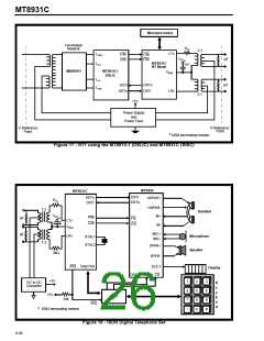
Interfacing to Non-Multiplexed Busses
Figure 18 illustrates the use of the SNIC in
conjunction with the MT9094 to implement a 2B+
D, ISDN telephone set. The MT9094 provides such
features as A/D and D/A conversion, handset
interface, handsfree operation and tone ringer. PCM
encoded voice is passed from the MT9094 to the
SNIC via the ST-BUS port for transmission on one of
the B-channels. The second B-channel is available
for transmission of data. These two devices have
been designed to connect together with virtually no
interconnection components.
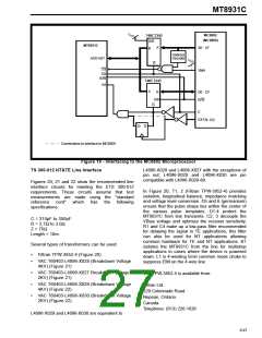
The microprocessor interface for the SNIC was
designed around a multiplexed bus architecture
which may be found with most Intel processors/
controllers or a few Motorola processors. In the
event that your choice of processors is restricted, a
simple application circuit can convert the non-
multiplexed bussing to that of
a
multiplexed
architecture. Figure 19 provides an to interface the
MC6802 or the MC6809 microprocessors.
Both the MT8931C and MT9094 are controlled and
monitored by a microprocessor to implement various
+5V
1.5 nF
MT8931C
MT8971B/72B
DSTo
DSTi
390 Ω
22 nF
RTx
DSTi
DSTo
LOUT
LTx
2:1
1:2*
F0b
F0b
C4b
+5V
‡
R
R
C4b
47 Ω
+5V
10µF
1.0 µF
LIN
VBias
MS0
MS1
MS2
10.24 MHz XTAL
NT
‡
OSC1
Rsti
10kΩ
1:2*
VREF
VBias
0.33 µF
Star
OSC2
LRx
33 pF
33 pF
0.33µF
0.33µF
+5V
Microprocessor
DC to DC
Converter
‡
100Ω terminating resistor
Figure 16 - NT1 Function
9-95

 MITEL [ MITEL NETWORKS CORPORATION ]