‡
Pre lim in a ry
MT9V012 - 1/6-In ch VGA CMOS Dig it a l Im a g e Se n so r
Fe a t u re De scrip t io n
t
adjusted to avoid banding in the image caused by light flicker. This means that INT
must be a multiple of 1/ 120 of a second under 60Hz flicker, and a multiple of 1/ 100 of a
second under 50Hz flicker.
Ma xim u m Sh u t t e r De la y
The shutter delay can be used to reduce the integration time. A programmed value of N
reduces the integration time by N master clock periods. The maximum shutter delay is
set by the row time and the sample time, as shown in the equation below:
max shutter delay
where:
=
=
=
Row Time - Shutter Overhead
Row Time
(Reg0x04 + HBLANK_REG) * PIXCLK_PERIOD from Table 3 on page 12
331 master clock periods
Shutter Overhead
with default settings:
max shutter delay
=
=
(884 * 2) - 331
1437 master clock periods
If the value in this register exceeds the maximum value given by this equation, the sen-
sor may not generate an image.
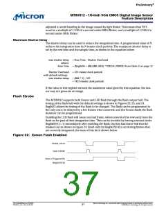
Fla sh St ro b e
The MT9V012 supports both Xenon and LED flash through the flash output ball. The
timing of the flash ball with the default settings is shown in Figures 22, 23, and 24.
Reg0x23 allows the timing of the flash to be changed. The flash can be programmed to
fire only once; be delayed by a few frames when asserted; and (for Xenon flash) the flash
duration can be programmed.
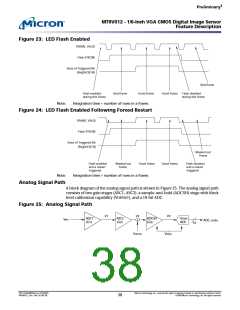
Enabling the LED flash will cause one bad frame, where several of the rows only have the
flash on for part of their integration time. This can be avoided by forcing a restart (write
Reg0x0D[1] = 1) immediately after enabling the flash; the first bad frame will then be
masked out as shown in Figure 24. Read-only bit Reg0x23[14] is set during frames that
are correctly integrated; the state of this bit is shown below.
Fig u re 22: Xe n o n Fla sh En a b le d
FRAME_VALID
Flash STROBE
State of Triggered Bit
(Reg0x23[14])
PDF: 814eb99f/Source: 8175e929
MT9V012_2.fm - Rev. B 2/05 EN
Micron Technology, Inc., reserves the right to change products or specifications without notice.
©2004 Micron Technology, Inc. All rights reserved.
37

 MICRON [ MICRON TECHNOLOGY ]