‡
Pre lim in a ry
MT9V012 - 1/6-In ch VGA CMOS Dig it a l Im a g e Se n so r
Fe a t u re De scrip t io n
Re a d o u t Mo d e s
Co lu m n Mirro r Im a g e
By setting Reg0x20[1] = 1, the readout order of the columns will be reversed, as shown in
Figure 16. The starting color is preserved when mirroring the columns.
Ro w Mirro r Im a g e
By setting Reg0x20[0] = 1, the readout order of the rows will be reversed as shown in
Figure 17. The starting color is preserved when mirroring the rows.
Fig u re 16: Six Pixe ls in No rm a l a n d Co lu m n Mirro r Re a d o u t Mo d e s
LINE_VALID
Normal Readout
G0 [9:0] R0 [9:0] G1 [9:0] R1 [9:0] G2 [9:0] R2 [9:0]
DOUT9–DOUT0
Reverse Readout
OUT9–DOUT
G3 [9:0] R2 [9:0] G2 [9:0] R1 [9:0] G1 [9:0] R0 [9:0]
D
0
Fig u re 17: Six Ro w s in No rm a l a n d Ro w Mirro r Re a d o u t Mo d e s
FRAME_VALID
Normal Readout
Row0 [9:0] Row1 [9:0] Row2 [9:0] Row3 [9:0] Row4 [9:0] Row5 [9:0]
DOUT9–DOUT0
Reverse Readout
OUT9–DOUT
Row6 [9:0] Row5 [9:0] Row4 [9:0] Row3 [9:0] Row2 [9:0] Row1 [9:0]
D
0
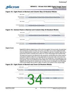
Co lu m n a n d Ro w Skip
By setting Reg0x20[2] = 1 (Reg0x21 in context A), only half of the columns set will be read
out. An example is shown in Figure 18. Only columns with bit 1 equal to “0” will be read
out (xxxxxxx0x). The row skip works in the same way and will only read out rows with bit
1 equal to “0.” Row skip mode is enabled by setting Reg0x20[4]. For both row and col-
umn skips, the number of rows or columns read out will be half of what is set in Reg0x03
or Reg0x04, respectively.
The sensor can also be programmed to only read out a quarter of the specified window
size by setting Reg0x20[5:4], as shown in Figure 19. In all cases, the row and column
sequencing ensures that the Bayer pattern is preserved.
PDF: 814eb99f/Source: 8175e929
MT9V012_2.fm - Rev. B 2/05 EN
Micron Technology, Inc., reserves the right to change products or specifications without notice.
33
©2004 Micron Technology, Inc. All rights reserved.

 MICRON [ MICRON TECHNOLOGY ]