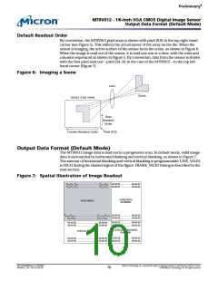
‡
Pre lim in a ry
MT9V012 - 1/6-In ch VGA CMOS Dig it a l Im a g e Se n so r
Ou t p u t Da t a Fo rm a t (Se ria l Mo d e )
Ou t p u t Da t a Fo rm a t (Se ria l Mo d e )
The MT9V012 image data is read out in a progressive scan. In serial mode, valid image
data is surrounded by horizontal blanking and vertical blanking, as shown in Figure 7 on
page 10. However, unlike default mode, serial mode provides pixel data and timing
strobes combined into a single serial bit stream. Electrically, this bit stream uses LVDS
on the DOUTP and DOUTN output signals.
In serial mode, each pixel is encoded as a 12-bit value by adding a start bit and a stop bit.
The sensor CLKIN input runs at the serial bit-rate and is used within the sensor to clock
a data serializer circuit; it is divided within the sensor so that most of the circuitry runs at
the same rate as in default mode. In serial mode, the pixel rate is fixed at one-half the
input frequency; therefore, CLKIN runs at 6 x 27 MHz = 162 MHz.
Ou t p u t Da t a Tim in g (Se ria l Mo d e )
The default frame timing in serial mode is identical to the frame timing in default mode.
A special three-character “start-of-frame” sequence—0x3FF, 0x0, and 0x3FF—is trans-
mitted to indicate the assertion of FRAME_VALID. Pixel data, LINE_VALID, and
FRAME_VALID can be reconstructed externally by detecting the start-of-frame
sequence, and using a state machine and counters to identify the active regions of the
frame.
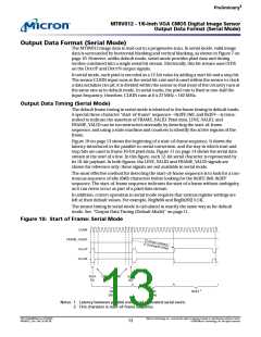
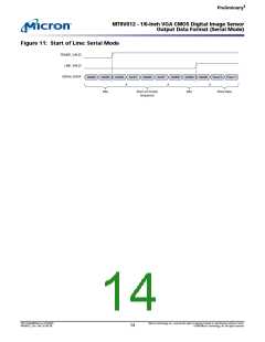
Figure 10 on page 13 shows the beginning of a start-of-frame sequence. It shows the
latency introduced in the parallel-to-serial conversion, and the way in which start and
stop bits are used to frame 10-bit pixel data. Figure 11 on page 14 shows the serial data
stream at the start of a line. In this figure, each 12-bit serial character is represented by
its 10-bit payload. In both figures, the LINE_VALID and FRAME_VALID signals are
shown for reference only; these signals are not available in serial mode.
The most effective method for detecting the start-of-frame sequence is to look for a con-
tinuous sequence of idle (0x0) characters before looking for the 0x3FF, 0x0, 0x3FF
sequence. The start-of-frame sequence indicates the start of a frame without ambiguity,
as it can never occur as part of a pixel data stream.
In addition, correct operation in serial mode requires that various register settings are
left at their default values. For example, Reg0x0A and Reg0x20[15:14].
The sensor timing in serial mode is calculated in exactly the same way as for default
mode. See “Output Data Timing (Default Mode)” on page 11.
Fig u re 10: St a rt o f Fra m e : Se ria l Mo d e
CLKIN
FRAME_VALID
DOUTP
DOUTN
LSB
MSB
Start
Bit
Stop
Bit
0x0
(Idle)
0x0
(Idle)
0x3FF 2
Notes: 1. Latency between parallel event and equivalent serial event.
2. First character in start-of-frame sequence.
PDF: 814eb99f/Source: 8175e929
MT9V012_2.fm - Rev. B 2/05 EN
Micron Technology, Inc., reserves the right to change products or specifications without notice.
©2004 Micron Technology, Inc. All rights reserved.
13

 MICRON [ MICRON TECHNOLOGY ]