‡
Pre lim in a ry
MT9V012 - 1/6-In ch VGA CMOS Dig it a l Im a g e Se n so r
Pixe l Arra y St ru ct u re
Pixe l Arra y St ru ct u re
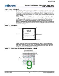
The MT9V012 pixel array is configured as 695 columns by 504 rows (shown in Figure 4).
The first 34 columns and the first 14 rows of pixels are optically black, and are used for
the automatic black level adjustment (“Black Level Calibration” on page 40). The last 12
columns and the last row of pixels are also optically black. The optically active pixels are
used as follows:
A VGA image (640 columns by 480 rows) is generated, starting at row 18, column 38. A
four-pixel boundary of active pixels can be enabled around the image to avoid boundary
effects during color interpolation and correction. An additional row and column of
active pixels is also provided for use during horizontally- and/ or vertically mirrored
readout. During mirrored readout, the region of active pixels that is used to generate the
image is offset by one pixel in each mirrored direction so that the readout always starts
on the same color pixel.
Fig u re 4: Pixe l Arra y
(0,0)
14 black rows
Oversize VGA
(640 x 480)
+ 4 pixel border
12 black columns
34 black columns
+1 row/column for mirroring
= 649 x 489 active pixels
1 black row
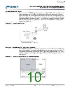
The MT9V012 uses a Bayer color pattern, as shown in Figure 5. The even-numbered
rows contain green and red color pixels; odd-numbered rows contain blue and green
color pixels. Even-numbered columns contain green and blue color pixels; odd-num-
bered columns contain red and green color pixels.
Fig u re 5: Pixe l Co lo r Pa t t e rn De t a il (To p Rig h t Co rn e r)
Column Readout Direction
.
.
.
Black Pixels
Pixel
(34,14)
G1 R G1 R G1 R G1
B G2 B G2 B G2 B
G1 R G1 R G1 R G1
B G2 B G2 B G2 B
G1 R G1 R G1 R G1
B G2 B G2 B G2 B
Row
Readout
Direction
...
PDF: 814eb99f/Source: 8175e929
MT9V012_2.fm - Rev. B 2/05 EN
Micron Technology, Inc., reserves the right to change products or specifications without notice.
©2004 Micron Technology, Inc. All rights reserved.
9

 MICRON [ MICRON TECHNOLOGY ]