ADVANCE
4 MEG x 8, 4 MEG x 9, 2 MEG x 18, 1 MEG x 36
1.8V VDD, HSTL, QDRIIb2 SRAM
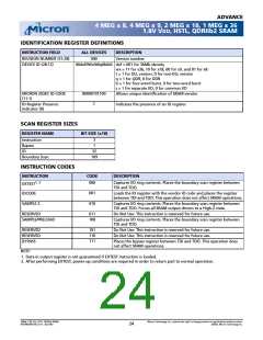
IDENTIFICATION REGISTER DEFINITIONS
INSTRUCTION FIELD
ALL DEVICES
DESCRIPTION
REVISION NUMBER (31:28)
DEVICE ID (28:12)
000
Version number.
00def0Wx0t0q0b0s0 def = 001 for 36Mb density
wx = 11 for x36, 10 for x18, 00 for x9, and 01 for x8
t = 1 for DLL version, 0 for non-DLL version
q = 1 for QDR, 0 for DDR
b = 1 for four-word burst, 0 for two-word burst
s = 1 for separate I/O, 0 for common I/O
00000101100
1
MICRON JEDEC ID CODE
(11:1)
Allows unique identification of SRAM vendor.
ID Register Presence
Indicator (0)
Indicates the presence of an ID register.
SCAN REGISTER SIZES
REGISTER NAME
BIT SIZE (x18)
3
1
Instruction
Bypass
32
109
ID
Boundary Scan
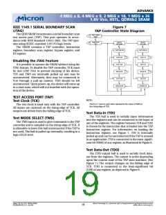
INSTRUCTION CODES
INSTRUCTION
CODE
DESCRIPTION
EXTEST1, 2
000
Captures I/O ring contents. Places the boundary scan register between
TDI and TDO.
001
010
IDCODE
Loads the ID register with the vendor ID code and places the register
between TDI and TDO. This operation does not affect SRAM operations.
SAMPLE Z
Captures I/O ring contents. Places the boundary scan register between
TDI and TDO. Forces all SRAM output drivers to a High-Z state.
RESERVED
011
100
Do Not Use: This instruction is reserved for future use.
SAMPLE/PRELOAD
Captures I/O ring contents. Places the boundary scan register between
TDI and TDO.
101
110
111
RESERVED
RESERVED
BYPASS
Do Not Use: This instruction is reserved for future use.
Do Not Use: This instruction is reserved for future use.
Places the bypass register between TDI and TDO. This operation does
not affect SRAM operations.
NOTE:
1. Data in output register is not guaranteed if EXTEST instruction is loaded.
2. After performing EXTEST, power-up conditions are required in order to return part to normal operation.
36Mb: 1.8V VDD, HSTL, QDRIIb2 SRAM
MT54W2MH18B_A.fm - Rev 9/02
Micron Technology, Inc., reserves the right to change products or specifications without notice.
©2002, Micron Technology Inc.
24

 MICRON [ MICRON TECHNOLOGY ]