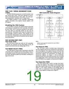
ADVANCE
4 MEG x 8, 4 MEG x 9, 2 MEG x 18, 1 MEG x 36
1.8V VDD, HSTL, QDRIIb2 SRAM
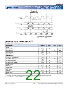
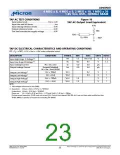
TAP AC TEST CONDITIONS
Figure 10
TAP AC Output Load Equivalent
Input pulse levels . . . . . . . . . . . . . . . . . . . . . VSS to 1.8V
Input rise and fall times . . . . . . . . . . . . . . . . . . . . . .1ns
Input timing reference levels . . . . . . . . . . . . . . . . . 0.9V
Output reference levels . . . . . . . . . . . . . . . . . . . . . . 0.9V
Test load termination supply voltage. . . . . . . . . . 0.9V
0.9V
50Ω
TDO
ZO= 50Ω
20pF
TAP DC ELECTRICAL CHARACTERISTICS AND OPERATING CONDITIONS
0ºC
?
TA
?
+70ºC; +1.7V ? VDD ? +1.9V unless otherwise noted
DESCRIPTION
CONDITIONS
SYMBOL
VIH
MIN
1.3
MAX
VDD + 0.3
0.5
UNITS NOTES
Input High (Logic 1) Voltage1,2
Input Low (Logic 0) Voltage1,2
Input Leakage Current
V
V
1, 2
1, 2
VIL
-0.3
0V ? VIN ? VDD
ILI
-5.0
-5.0
5.0
5.0
µA
µA
Output Leakage Current
Output(s) disabled,
ILO
0V ? VIN ? VDDQ (DQx)
Output Low Voltage1
Output Low Voltage1
Output High Voltage1
Output High Voltage1
NOTE:
IOLC = 100µA
VOL1
VOL2
VOH1
VOH1
0.2
0.4
V
V
V
V
1
1
1
1
IOLT = 2mA
IOHC = -100µA
IOHT = -2mA
1.6
1.4
1. 1All voltages referenced to Vss (GND).
t
2. Overshoot:
VIH(AC) ? VDD + 0.7V for t ? KHKH/2
t
Undershoot: VIL(AC)ꢁO -0.5V for t ? KHKH/2
Power-up: VIH ? VDDQ + 0.3V and VDD ? +1.7V and VDDQ ? 1.4V for t ? 200ms
During normal operation, VDDQ must not exceed VDD. Control input signals (R#, W#, etc.) may not have pulse widths less than
t
t
KHKL (MIN) or operate at frequencies exceeding KF (MAX).
36Mb: 1.8V VDD, HSTL, QDRIIb2 SRAM
MT54W2MH18B_A.fm - Rev 9/02
Micron Technology, Inc., reserves the right to change products or specifications without notice.
©2002, Micron Technology Inc.
23

 MICRON [ MICRON TECHNOLOGY ]