64Mb : x4, x8, x16
SDRAM
1
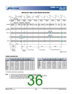
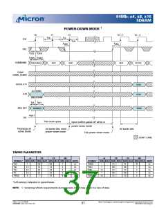
POWER-DOWN MODE
T0
T1
T2
Tn + 1
Tn + 2
( (
t
t
) )
CK
CL
CLK
CKE
( (
) )
t
CH
t
t
CKS
CKS
( (
) )
t
t
CKS CKH
t
t
CMS CMH
( (
) )
COMMAND
PRECHARGE
NOP
NOP
NOP
ACTIVE
( (
) )
( (
) )
DQM /
( (
) )
DQML, DQMH
( (
) )
A0-A9, A11
A10
ROW
ROW
( (
) )
ALL BANKS
( (
) )
( (
) )
SINGLE BANK
t
t
AH
AS
( (
) )
BA0, BA1
DQ
BANK
BANK(S)
( (
) )
High-Z
( (
) )
Two clock cycles
Input buffers gated off while in
power-down mode
Precharge all
active banks
All banks idle
All banks idle, enter
power-down mode
Exit power-down mode
DON’T CARE
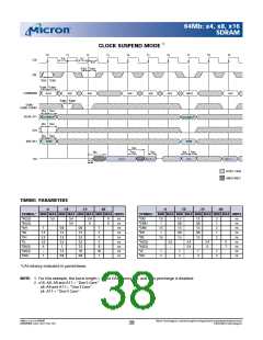
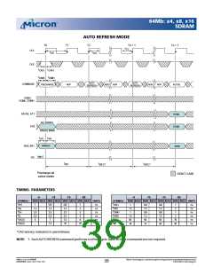
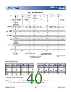
TIMING PARAMETERS
-6
-7 E
-7 5
-8 E
-6
-7 E
-7 5
-8 E
SYMBOL* MIN MAX MIN MAX MIN MAX MIN MAX UNITS
SYMBOL* MIN MAX MIN MAX MIN MAX MIN MAX UNITS
t
t
AH
AS
1
0.8
1.5
2.5
2.5
7
0.8
1.5
2.5
2.5
7.5
1
2
3
3
8
ns
ns
ns
ns
ns
CK(2)
CKH
CKS
–
1
7.5
0.8
1.5
0.8
1.5
10
0.8
1.5
0.8
1.5
10
1
ns
ns
ns
ns
ns
t
t
t
t
t
t
t
t
1.5
2.5
2.5
6
CH
1.5
1
2
CL
CMH
CMS
1
CK(3)
1.5
2
*CAS latency indicated in parentheses.
NOTE: 1. Violating refresh requirements during power-down may result in a loss of data.
64Mb: x4, x8, x16 SDRAM
64MSDRAM_F.p65 – Rev. F; Pub. 1/03
Micron Technology, Inc., reservesthe right to change productsor specificationswithout notice.
©2003, Micron Technology, Inc.
37

 MICRON [ MICRON TECHNOLOGY ]