PIC24FJ64GA104 FAMILY
6.2.1
POR AND LONG OSCILLATOR
START-UP TIMES
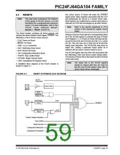
6.3
Special Function Register Reset
States
The oscillator start-up circuitry and its associated delay
timers are not linked to the device Reset delays that
occur at power-up. Some crystal circuits (especially
low-frequency crystals) will have a relatively long
start-up time. Therefore, one or more of the following
conditions is possible after SYSRST is released:
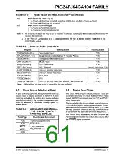
Most of the Special Function Registers (SFRs) associ-
ated with the PIC24F CPU and peripherals are reset to a
particular value at a device Reset. The SFRs are
grouped by their peripheral or CPU function and their
Reset values are specified in each section of this manual.
The Reset value for each SFR does not depend on the
type of Reset with the exception of four registers. The
Reset value for the Reset Control register, RCON, will
depend on the type of device Reset. The Reset value
for the Oscillator Control register, OSCCON, will
depend on the type of Reset and the programmed
values of the FNOSC bits in Flash Configuration
Word 2 (CW2); see Table 6-2. The RCFGCAL and
NVMCON registers are only affected by a POR.
• The oscillator circuit has not begun to oscillate.
• The Oscillator Start-up Timer has not expired (if a
crystal oscillator is used).
• The PLL has not achieved a lock (if PLL is used).
The device will not begin to execute code until a valid
clock source has been released to the system. There-
fore, the oscillator and PLL start-up delays must be
considered when the Reset delay time must be known.
6.4
Deep Sleep BOR (DSBOR)
6.2.2
FAIL-SAFE CLOCK MONITOR
(FSCM) AND DEVICE RESETS
Deep Sleep BOR is a very low-power BOR circuitry,
used when the device is in Deep Sleep mode. Due to
low-current consumption, accuracy may vary.
If the FSCM is enabled, it will begin to monitor the
system clock source when SYSRST is released. If a
valid clock source is not available at this time, the
device will automatically switch to the FRC Oscillator
and the user can switch to the desired crystal oscillator
in the Trap Service Routine (TSR).
The DSBOR trip point is around 2.0V. DSBOR is
enabled by configuring CW4 (DSBOREN) = 1. DSBOR
will re-arm the POR to ensure the device will reset if VDD
drops below the POR threshold.
2010 Microchip Technology Inc.
DS39951C-page 63

 MICROCHIP [ MICROCHIP ]