PIC24FJ64GA104 FAMILY
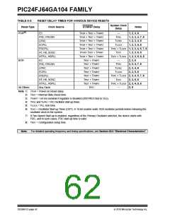
TABLE 6-3:
Reset Type
POR(6)
RESET DELAY TIMES FOR VARIOUS DEVICE RESETS
System Clock
Delay
Clock Source
SYSRST Delay
Notes
1, 2, 3, 8
EC
TPOR + TRST + TPWRT
TPOR + TRST + TPWRT
TPOR + TRST + TPWRT
TPOR + TRST + TPWRT
TPOR + TRST + TPWRT
TPOR+ TRST + TPWRT
TPOR + TRST + TPWRT
TRST + TPWRT
—
FRC, FRCDIV
LPRC
TFRC
TLPRC
TLOCK
1, 2, 3, 4, 7, 8
1, 2, 3, 4, 8
1, 2, 3, 5, 8
ECPLL
FRCPLL
TFRC + TLOCK 1, 2, 3, 4, 5, 7, 8
TOST 1, 2, 3, 6, 8
TOST + TLOCK 1, 2, 3, 5, 6, 8
XT, HS, SOSC
XTPLL, HSPLL
EC
BOR
—
2, 3, 8
FRC, FRCDIV
LPRC
TRST + TPWRT
TFRC
TLPRC
TLOCK
2, 3, 4, 7, 8
2, 3, 4, 8
2, 3, 5, 8
TRST + TPWRT
ECPLL
TRST + TPWRT
FRCPLL
TRST + TPWRT
TFRC + TLOCK 2, 3, 4, 5, 7, 8
TOST 2, 3, 6, 8
TFRC + TLOCK 2, 3, 4, 5, 8
2, 8
XT, HS, SOSC
XTPLL, HSPLL
Any Clock
TRST + TPWRT
TRST + TPWRT
All Others
TRST
—
Note 1: TPOR = Power-on Reset delay.
2: TRST = Internal State Reset time.
3: TPWRT = 64 ms nominal if regulator is disabled (DISVREG tied to VDD).
4: TFRC and TLPRC = RC Oscillator start-up times.
5: TLOCK = PLL lock time.
6: TOST = Oscillator Start-up Timer (OST). A 10-bit counter waits 1024 oscillator periods before releasing the
oscillator clock to the system.
7: If Two-Speed Start-up is enabled, regardless of the Primary Oscillator selected, the device starts with
FRC, and in such cases, FRC start-up time is valid.
8: TRST = Configuration setup time.
Note: For detailed operating frequency and timing specifications, see Section 28.0 “Electrical Characteristics”.
DS39951C-page 62
2010 Microchip Technology Inc.

 MICROCHIP [ MICROCHIP ]