PIC24FJ64GA104 FAMILY
Any active source of Reset will make the SYSRST
signal active. Many registers associated with the CPU
6.0
RESETS
Note:
This data sheet summarizes the features
of this group of PIC24F devices. It is not
intended to be a comprehensive reference
source. For more information, refer to the
“PIC24F Family Reference Manual”,
Section 7. “Reset” (DS39712).
and peripherals are forced to a known Reset state.
Most registers are unaffected by a Reset; their status is
unknown on POR and unchanged by all other Resets.
Note:
Refer to the specific peripheral or CPU
section of this manual for register Reset
states.
The Reset module combines all Reset sources and
controls the device Master Reset Signal, SYSRST. The
following is a list of device Reset sources:
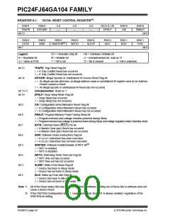
All types of device Reset will set a corresponding status
bit in the RCON register to indicate the type of Reset
(see Register 6-1). A Power-on Reset will clear all bits,
except for the BOR and POR bits (RCON<1:0>), which
are set. The user may set or clear any bit at any time
during code execution. The RCON bits only serve as
status bits. Setting a particular Reset status bit in
software will not cause a device Reset to occur.
• POR: Power-on Reset
• MCLR: Pin Reset
• SWR: RESETInstruction
• WDT: Watchdog Timer Reset
• BOR: Brown-out Reset
The RCON register also has other bits associated with
the Watchdog Timer and device power-saving states.
The function of these bits is discussed in other sections
of this data sheet.
• CM: Configuration Mismatch Reset
• TRAPR: Trap Conflict Reset
• IOPUWR: Illegal Opcode Reset
• UWR: Uninitialized W Register Reset
Note:
The status bits in the RCON register
should be cleared after they are read so
that the next RCON register value after a
device Reset will be meaningful.
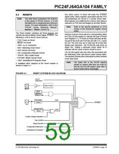
A simplified block diagram of the Reset module is
shown in Figure 6-1.
FIGURE 6-1:
RESET SYSTEM BLOCK DIAGRAM
RESET
Instruction
Glitch Filter
MCLR
WDT
Module
Sleep or Idle
POR
VDD Rise
Detect
SYSRST
VDD
Brown-out
Reset
BOR
Enable Voltage Regulator
Trap Conflict
Illegal Opcode
Configuration Mismatch
Uninitialized W Register
2010 Microchip Technology Inc.
DS39951C-page 59

 MICROCHIP [ MICROCHIP ]