PIC24FJ64GA104 FAMILY
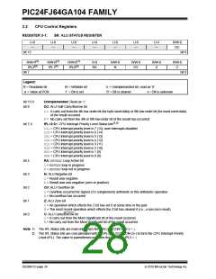
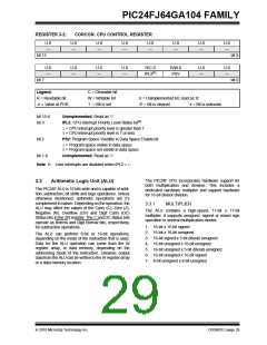
REGISTER 3-2:
CORCON: CPU CONTROL REGISTER
U-0
—
U-0
—
U-0
—
U-0
—
U-0
—
U-0
—
U-0
—
U-0
—
bit 15
bit 8
bit 0
U-0
—
U-0
—
U-0
—
U-0
—
R/C-0
IPL3(1)
R/W-0
PSV
U-0
—
U-0
—
bit 7
Legend:
C = Clearable bit
W = Writable bit
‘1’ = Bit is set
R = Readable bit
-n = Value at POR
U = Unimplemented bit, read as ‘0’
‘0’ = Bit is cleared x = Bit is unknown
bit 15-4
bit 3
Unimplemented: Read as ‘0’
IPL3: CPU Interrupt Priority Level Status bit(1)
1= CPU interrupt priority level is greater than 7
0= CPU interrupt priority level is 7 or less
bit 2
PSV: Program Space Visibility in Data Space Enable bit
1= Program space visible in data space
0= Program space not visible in data space
bit 1-0
Unimplemented: Read as ‘0’
Note 1: User interrupts are disabled when IPL3 = 1.
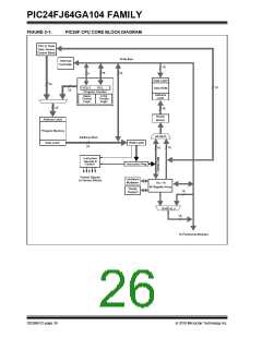
The PIC24F CPU incorporates hardware support for
both multiplication and division. This includes a
dedicated hardware multiplier and support hardware
for 16-bit divisor division.
3.3
Arithmetic Logic Unit (ALU)
The PIC24F ALU is 16 bits wide and is capable of addi-
tion, subtraction, bit shifts and logic operations. Unless
otherwise mentioned, arithmetic operations are 2’s
complement in nature. Depending on the operation, the
ALU may affect the values of the Carry (C), Zero (Z),
Negative (N), Overflow (OV) and Digit Carry (DC)
Status bits in the SR register. The C and DC Status bits
operate as Borrow and Digit Borrow bits, respectively,
for subtraction operations.
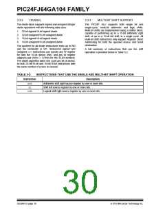
3.3.1
MULTIPLIER
The ALU contains a high-speed, 17-bit x 17-bit
multiplier. It supports unsigned, signed or mixed sign
operation in several multiplication modes:
1. 16-bit x 16-bit signed
2. 16-bit x 16-bit unsigned
The ALU can perform 8-bit or 16-bit operations,
depending on the mode of the instruction that is used.
Data for the ALU operation can come from the W
register array, or data memory, depending on the
addressing mode of the instruction. Likewise, output
data from the ALU can be written to the W register array
or a data memory location.
3. 16-bit signed x 5-bit (literal) unsigned
4. 16-bit unsigned x 16-bit unsigned
5. 16-bit unsigned x 5-bit (literal) unsigned
6. 16-bit unsigned x 16-bit signed
7. 8-bit unsigned x 8-bit unsigned
2010 Microchip Technology Inc.
DS39951C-page 29

 MICROCHIP [ MICROCHIP ]