PIC24FJ64GA104 FAMILY
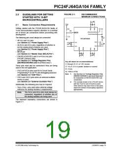
FIGURE 2-1:
RECOMMENDED
MINIMUM CONNECTIONS
2.0
2.1
GUIDELINES FOR GETTING
STARTED WITH 16-BIT
MICROCONTROLLERS
(2)
C2
VDD
Basic Connection Requirements
Getting started with the PIC24FJ64GA104 family of
16-bit microcontrollers requires attention to a minimal
set of device pin connections before proceeding with
development.
(1)
(1)
R1
R2
(EN/DIS)VREG
VCAP/VDDCORE
MCLR
C1
The following pins must always be connected:
C7
PIC24FXXXX
• All VDD and VSS pins
(see Section 2.2 “Power Supply Pins”)
VDD
VSS
VSS
VDD
(2)
(2)
C3
C6
• All AVDD and AVSS pins, regardless of whether or
not the analog device features are used
(see Section 2.2 “Power Supply Pins”)
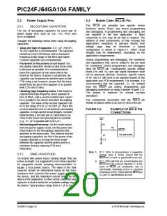
• MCLR pin
(see Section 2.3 “Master Clear (MCLR) Pin”)
(2)
(2)
C4
C5
• ENVREG/DISVREG and VCAP/VDDCORE pins
(PIC24FJ devices only)
(see Section 2.4 “Voltage Regulator Pins
(ENVREG/DISVREG and VCAP/VDDCORE)”)
Key (all values are recommendations):
C1 through C6: 0.1 F, 20V ceramic
These pins must also be connected if they are being
used in the end application:
C7: 10 F, 6.3V or greater, tantalum or ceramic
R1: 10 kΩ
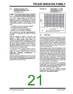
• PGECx/PGEDx pins used for In-Circuit Serial
Programming™ (ICSP™) and debugging purposes
(see Section 2.5 “ICSP Pins”)
R2: 100Ω to 470Ω
Note 1: See Section 2.4 “Voltage Regulator Pins
(ENVREG/DISVREG and VCAP/VDDCORE)”
for explanation of ENVREG/DISVREG pin
connections.
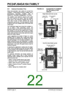
• OSCI and OSCO pins when an external oscillator
source is used
(see Section 2.6 “External Oscillator Pins”)
2: The example shown is for a PIC24F device
with five VDD/VSS and AVDD/AVSS pairs.
Other devices may have more or less pairs;
adjust the number of decoupling capacitors
appropriately.
Additionally, the following pins may be required:
• VREF+/VREF- pins used when external voltage
reference for analog modules is implemented
Note:
The AVDD and AVSS pins must always be
connected, regardless of whether any of
the analog modules are being used.
The minimum mandatory connections are shown in
Figure 2-1.
2010 Microchip Technology Inc.
DS39951C-page 19

 MICROCHIP [ MICROCHIP ]