PIC24FJ64GA104 FAMILY
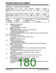
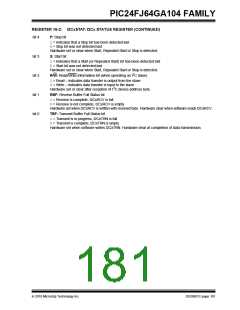
REGISTER 16-2: I2CxSTAT: I2Cx STATUS REGISTER
R-0, HSC R-0, HSC
ACKSTAT TRSTAT
bit 15
U-0
—
U-0
—
U-0
—
R/C-0, HS
BCL
R-0, HSC
GCSTAT
R-0, HSC
ADD10
bit 8
bit 0
R/C-0, HS R/C-0, HS R-0, HSC R/C-0, HSC R/C-0, HSC
R-0, HSC
R/W
R-0, HSC
RBF
R-0, HSC
TBF
IWCOL
bit 7
I2COV
D/A
P
S
Legend:
C = Clearable bit
W = Writable bit
‘1’ = Bit is set
HS = Hardware Settable bit
U = Unimplemented bit, read as ‘0’
‘0’ = Bit is cleared x = Bit is unknown
HSC = Hardware Settable/Clearable bit
R = Readable bit
-n = Value at POR
bit 15
ACKSTAT: Acknowledge Status bit
1= NACK was detected last
0= ACK was detected last
Hardware set or clear at end of Acknowledge.
bit 14
TRSTAT: Transmit Status bit
(When operating as I2C master. Applicable to master transmit operation.)
1= Master transmit is in progress (8 bits + ACK)
0= Master transmit is not in progress
Hardware set at the beginning of master transmission. Hardware clear at the end of slave Acknowledge.
bit 13-11 Unimplemented: Read as ‘0’
bit 10
bit 9
bit 8
bit 7
bit 6
bit 5
BCL: Master Bus Collision Detect bit
1= A bus collision has been detected during a master operation
0= No collision
Hardware set at detection of bus collision.
GCSTAT: General Call Status bit
1= General call address was received
0= General call address was not received
Hardware set when the address matches the general call address. Hardware clear at Stop detection.
ADD10: 10-Bit Address Status bit
1= 10-bit address was matched
0= 10-bit address was not matched
Hardware set at the match of 2nd byte of matched 10-bit address. Hardware clear at Stop detection.
IWCOL: Write Collision Detect bit
1= An attempt to write to the I2CxTRN register failed because the I2C module is busy
0= No collision
Hardware set at occurrence of write to I2CxTRN while busy (cleared by software).
I2COV: Receive Overflow Flag bit
1= A byte was received while the I2CxRCV register was still holding the previous byte
0= No overflow
Hardware set at attempt to transfer I2CxRSR to I2CxRCV (cleared by software).
D/A: Data/Address bit (when operating as I2C slave)
1= Indicates that the last byte received was data
0= Indicates that the last byte received was the the device address
Hardware clear occurs at device address match. Hardware set after a transmission finishes or at reception
of a slave byte.
DS39951C-page 180
2010 Microchip Technology Inc.

 MICROCHIP [ MICROCHIP ]