PIC24FJ64GA104 FAMILY
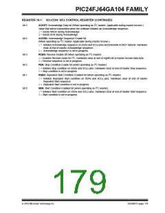
REGISTER 16-1: I2CxCON: I2Cx CONTROL REGISTER
R/W-0
I2CEN
U-0
—
R/W-0
R/W-1, HC
SCLREL
R/W-0
R/W-0
A10M
R/W-0
R/W-0
SMEN
I2CSIDL
IPMIEN
DISSLW
bit 15
bit 8
R/W-0
GCEN
R/W-0
R/W-0
R/W-0, HC
ACKEN
R/W-0, HC
RCEN
R/W-0, HC
PEN
R/W-0, HC
RSEN
R/W-0, HC
SEN
STREN
ACKDT
bit 7
bit 0
Legend:
HC = Hardware Clearable bit
W = Writable bit
R = Readable bit
U = Unimplemented bit, read as ‘0’
‘0’ = Bit is cleared x = Bit is unknown
-n = Value at POR
‘1’ = Bit is set
bit 15
I2CEN: I2Cx Enable bit
1= Enables the I2Cx module, and configures the SDAx and SCLx pins as serial port pins
0= Disables the I2Cx module. All I2C pins are controlled by port functions.
bit 14
bit 13
Unimplemented: Read as ‘0’
I2CSIDL: Stop in Idle Mode bit
1= Discontinues module operation when device enters an Idle mode
0= Continues module operation in Idle mode
bit 12
SCLREL: SCLx Release Control bit (when operating as I2C Slave)
1= Releases SCLx clock
0= Holds SCLx clock low (clock stretch)
If STREN = 1:
Bit is R/W (i.e., software may write ‘0’ to initiate stretch and write ‘1’ to release clock). Hardware clear
at beginning of slave transmission. Hardware clear at end of slave reception.
If STREN = 0:
Bit is R/S (i.e., software may only write ‘1’ to release clock). Hardware clear at beginning of slave
transmission.
bit 11
bit 10
bit 9
IPMIEN: Intelligent Platform Management Interface (IPMI) Enable bit
1= IPMI Support mode is enabled; all addresses Acknowledged
0= IPMI mode is disabled
A10M: 10-Bit Slave Addressing bit
1= I2CxADD is a 10-bit slave address
0= I2CxADD is a 7-bit slave address
DISSLW: Disable Slew Rate Control bit
1= Slew rate control is disabled
0= Slew rate control is enabled
bit 8
SMEN: SMBus Input Levels bit
1= Enables I/O pin thresholds compliant with the SMBus specification
0= Disables the SMBus input thresholds
bit 7
GCEN: General Call Enable bit (when operating as I2C slave)
1= Enables interrupt when a general call address is received in the I2CxRSR
(module is enabled for reception)
0= General call address is disabled
bit 6
STREN: SCLx Clock Stretch Enable bit (when operating as I2C slave)
Used in conjunction with the SCLREL bit.
1= Enables software or receive clock stretching
0= Disables software or receive clock stretching
DS39951C-page 178
2010 Microchip Technology Inc.

 MICROCHIP [ MICROCHIP ]