PIC24FJ64GA104 FAMILY
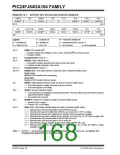
REGISTER 15-1: SPIxSTAT: SPIx STATUS AND CONTROL REGISTER
R/W-0
SPIEN(1)
U-0
—
R/W-0
U-0
—
U-0
—
R-0
R-0
R-0
SPISIDL
SPIBEC2
SPIBEC1
SPIBEC0
bit 15
bit 8
R-0
R/C-0, HS
SPIROV
R/W-0
R/W-0
R/W-0
R/W-0
R-0
R-0
SRMPT
SRXMPT
SISEL2
SISEL1
SISEL0
SPITBF
SPIRBF
bit 7
bit 0
Legend:
C = Clearable bit
W = Writable bit
‘1’ = Bit is set
HS = Hardware Settable bit
U = Unimplemented bit, read as ‘0’
‘0’ = Bit is cleared x = Bit is unknown
R = Readable bit
-n = Value at POR
bit 15
SPIEN: SPIx Enable bit(1)
1= Enables module and configures SCKx, SDOx, SDIx and SSx as serial port pins
0= Disables module
bit 14
bit 13
Unimplemented: Read as ‘0’
SPISIDL: Stop in Idle Mode bit
1= Discontinue module operation when device enters Idle mode
0= Continue module operation in Idle mode
bit 12-11
bit 10-8
Unimplemented: Read as ‘0’
SPIBEC<2:0>: SPIx Buffer Element Count bits (valid in Enhanced Buffer mode)
Master mode:
Number of SPI transfers that are pending.
Slave mode:
Number of SPI transfers that are unread.
bit 7
bit 6
SRMPT: Shift Register (SPIxSR) Empty bit (valid in Enhanced Buffer mode)
1= SPIx Shift register is empty and ready to send or receive
0= SPIx Shift register is not empty
SPIROV: Receive Overflow Flag bit
1= A new byte/word is completely received and discarded. The user software has not read the previous
data in the SPIxBUF register.
0= No overflow has occurred
bit 5
SRXMPT: Receive FIFO Empty bit (valid in Enhanced Buffer mode)
1= Receive FIFO is empty
0= Receive FIFO is not empty
bit 4-2
SISEL<2:0>: SPIx Buffer Interrupt Mode bits (valid in Enhanced Buffer mode)
111= Interrupt when SPIx transmit buffer is full (SPITBF bit is set)
110= Interrupt when last bit is shifted into SPIxSR; as a result, the TX FIFO is empty
101= Interrupt when the last bit is shifted out of SPIxSR; now the transmit is complete
100= Interrupt when one data is shifted into the SPIxSR; as a result, the TX FIFO has one open spot
011= Interrupt when SPIx receive buffer is full (SPIRBF bit is set)
010= Interrupt when SPIx receive buffer is 3/4 or more full
001= Interrupt when data is available in the receive buffer (SRMPT bit is set)
000= Interrupt when the last data in the receive buffer is read; as a result, the buffer is empty
(SRXMPT bit set)
Note 1: If SPIEN = 1, these functions must be assigned to available RPn pins before use. See Section 10.4
“Peripheral Pin Select (PPS)” for more information.
DS39951C-page 168
2010 Microchip Technology Inc.

 MICROCHIP [ MICROCHIP ]