PIC18F2450/4450
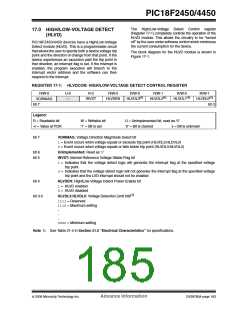
The High/Low-Voltage Detect Control register
(Register 17-1) completely controls the operation of the
HLVD module. This allows the circuitry to be “turned
off” by the user under software control which minimizes
the current consumption for the device.
17.0 HIGH/LOW-VOLTAGE DETECT
(HLVD)
PIC18F2450/4450 devices have a High/Low-Voltage
Detect module (HLVD). This is a programmable circuit
that allows the user to specify both a device voltage trip
point and the direction of change from that point. If the
device experiences an excursion past the trip point in
that direction, an interrupt flag is set. If the interrupt is
enabled, the program execution will branch to the
interrupt vector address and the software can then
respond to the interrupt.
The block diagram for the HLVD module is shown in
Figure 17-1.
REGISTER 17-1: HLVDCON: HIGH/LOW-VOLTAGE DETECT CONTROL REGISTER
R/W-0
U-0
—
R-0
R/W-0
R/W-0
HLVDL3(1)
R/W-1
HLVDL2(1)
R/W-0
HLVDL1(1)
R/W-1
HLVDL0(1)
VDIRMAG
IRVST
HLVDEN
bit 7
bit 0
Legend:
R = Readable bit
-n = Value at POR
W = Writable bit
‘1’ = Bit is set
U = Unimplemented bit, read as ‘0’
‘0’ = Bit is cleared x = Bit is unknown
bit 7
VDIRMAG: Voltage Direction Magnitude Select bit
1= Event occurs when voltage equals or exceeds trip point (HLVDL3:HLDVL0)
0= Event occurs when voltage equals or falls below trip point (HLVDL3:HLVDL0)
bit 6
bit 5
Unimplemented: Read as ‘0’
IRVST: Internal Reference Voltage Stable Flag bit
1= Indicates that the voltage detect logic will generate the interrupt flag at the specified voltage
trip point
0= Indicates that the voltage detect logic will not generate the interrupt flag at the specified voltage
trip point and the LVD interrupt should not be enabled
bit 4
HLVDEN: High/Low-Voltage Detect Power Enable bit
1= HLVD enabled
0= HLVD disabled
bit 3-0
HLVDL3:HLVDL0: Voltage Detection Limit bits(1)
1111= Reserved
1110= Maximum setting
.
.
.
0000= Minimum setting
Note 1: See Table 21-4 in Section 21.0 “Electrical Characteristics” for specifications.
© 2006 Microchip Technology Inc.
Advance Information
DS39760A-page 183

 MICROCHIP [ MICROCHIP ]