PIC18F2450/4450
FIGURE 17-3:
HIGH-VOLTAGE DETECT OPERATION (VDIRMAG = 1)
CASE 1:
HLVDIF may not be set
VHLVD
VDD
HLVDIF
Enable HLVD
IRVST
TIRVST
HLVDIF cleared in software
Internal Reference is stable
CASE 2:
VHLVD
VDD
HLVDIF
Enable HLVD
TIRVST
IRVST
Internal Reference is stable
HLVDIF cleared in software
HLVDIF cleared in software,
HLVDIF remains set since HLVD condition still exists
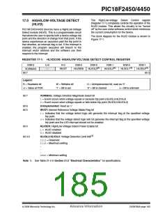
FIGURE 17-4:
TYPICAL
17.5 Applications
HIGH/LOW-VOLTAGE
DETECT APPLICATION
In many applications, the ability to detect a drop below
or rise above a particular threshold is desirable. For
example, the HLVD module could be periodically
enabled to detect Universal Serial Bus (USB) attach or
detach. This assumes the device is powered by a lower
voltage source than the USB when detached. An attach
would indicate a high-voltage detect from, for example,
3.3V to 5V (the voltage on USB) and vice versa for a
detach. This feature could save a design a few extra
components and an attach signal (input pin).
VA
VB
For general battery applications, Figure 17-4 shows a
possible voltage curve. Over time, the device voltage
decreases. When the device voltage reaches voltage,
VA, the HLVD logic generates an interrupt at time, TA.
The interrupt could cause the execution of an ISR,
which would allow the application to perform “house-
keeping tasks” and perform a controlled shutdown
before the device voltage exits the valid operating
range at TB. The HLVD, thus, would give the applica-
tion a time window, represented by the difference
between TA and TB, to safely exit.
TB
TA
Time
Legend:
VA = HLVD trip point
VB = Minimum valid device
operating voltage
DS39760A-page 186
Advance Information
© 2006 Microchip Technology Inc.

 MICROCHIP [ MICROCHIP ]