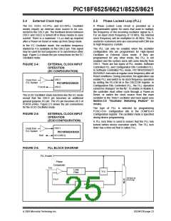
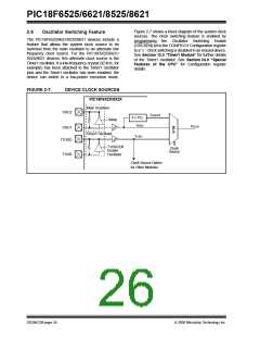
PIC18F6525/6621/8525/8621
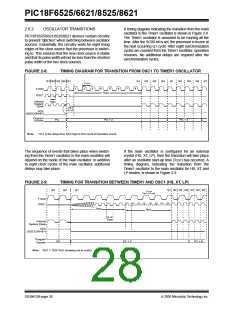
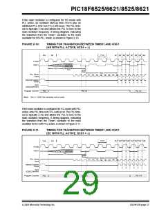
If the main oscillator is configured for HS mode with
PLL active, an oscillator start-up time (TOST) plus an
additional PLL time-out (TPLL) will occur. The PLL time-
out is typically 2 ms and allows the PLL to lock to the
main oscillator frequency. A timing diagram, indicating
the transition from the Timer1 oscillator to the main
oscillator for HS+PLL mode, is shown in Figure 2-10.
FIGURE 2-10:
TIMING FOR TRANSITION BETWEEN TIMER1 AND OSC1
(HS WITH PLL ACTIVE, SCS1 = 1)
TT1P
Q1 Q2 Q3 Q4 Q1 Q2 Q3 Q4
Q4
Q1
T1OSI
OSC1
TOST
TPLL
TOSC
1
TSCS
PLL Clock
Input
2
3
4
5
6
7
8
Internal System
Clock
SCS
(OSCCON<0>)
Program Counter
PC
PC + 2
PC + 4
Note: TOST = 1024 TOSC (drawing not to scale).
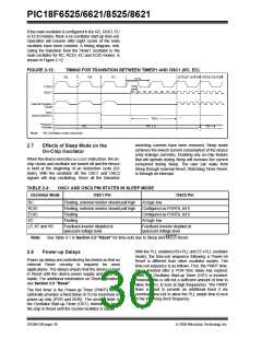
If the main oscillator is configured for EC mode with PLL
active, only PLL time-out (TPLL) will occur. The PLL time-
out is typically 2 ms and allows the PLL to lock to the
main oscillator frequency. A timing diagram, indicating
the transition from the Timer1 oscillator to the main
oscillator for EC with PLL active, is shown in Figure 2-11.
FIGURE 2-11:
TIMING FOR TRANSITION BETWEEN TIMER1 AND OSC1
(EC WITH PLL ACTIVE, SCS1 = 1)
TT1P
Q1 Q2 Q3 Q4 Q1 Q2 Q3 Q4
Q4
Q1
T1OSI
OSC1
TPLL
TOSC
TSCS
4
PLL Clock
Input
1
2
3
5
6
7
8
Internal System
Clock
SCS
(OSCCON<0>)
Program Counter
PC + 4
PC
PC + 2
2005 Microchip Technology Inc.
DS39612B-page 27

 MICROCHIP [ MICROCHIP ]