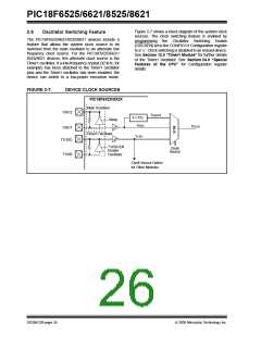
PIC18F6525/6621/8525/8621
2.4
External Clock Input
2.5
Phase Locked Loop (PLL)
The EC, ECIO, EC+PLL and EC+SPLL Oscillator
modes require an external clock source to be con-
nected to the OSC1 pin. The feedback device between
OSC1 and OSC2 is turned off in these modes to save
current. There is a maximum 1.5 µs start-up required
after a Power-on Reset or wake-up from Sleep mode.
A Phase Locked Loop circuit is provided as a
programmable option for users that want to multiply
the frequency of the incoming oscillator signal by 4.
For an input clock frequency of 10 MHz, the internal
clock frequency will be multiplied to 40 MHz. This is
useful for customers who are concerned with EMI due
to high-frequency crystals.
In the EC Oscillator mode, the oscillator frequency
divided by 4 is available on the OSC2 pin. This signal
may be used for test purposes or to synchronize other
logic. Figure 2-4 shows the pin connections for the EC
Oscillator mode.
The PLL can only be enabled when the oscillator
configuration bits are programmed for High-Speed
Oscillator or External Clock mode. If they are
programmed for any other mode, the PLL is not
enabled and the system clock will come directly from
OSC1. There are two types of PLL modes: Software
Controlled PLL and Configuration Bits Controlled PLL.
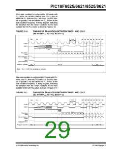
In Software Controlled PLL mode, PIC18F6525/6621/
8525/8621 executes at regular clock frequency after all
Reset conditions. During execution, the application can
enable PLL and switch to 4x clock frequency operation
by setting the PLLEN bit in the OSCCON register. In
Configuration Bits Controlled PLL, the PLL operation
cannot be changed “on-the-fly”. To enable or disable it,
the controller must either cycle through a Power-on
Reset, or switch the clock source from the main
oscillator to the Timer1 oscillator and back again (see
Section 2.6 “Oscillator Switching Feature” for
details).
FIGURE 2-4:
EXTERNAL CLOCK INPUT
OPERATION
(EC CONFIGURATION)
OSC1
Clock from
Ext. System
PIC18F6X2X/8X2X
OSC2
FOSC/4
The ECIO Oscillator mode functions like the EC mode
except that the OSC2 pin becomes an additional
general purpose I/O pin. The I/O pin becomes bit 6 of
PORTA (RA6). Figure 2-5 shows the pin connections
for the ECIO Oscillator mode.
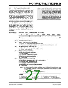
The type of PLL is selected by programming
FOSC<3:0> configuration bits in the CONFIG1H
Configuration register. The oscillator mode is specified
during device programming.
FIGURE 2-5:
EXTERNAL CLOCK INPUT
OPERATION
(ECIOCONFIGURATION)
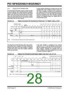
A PLL lock timer is used to ensure that the PLL has
locked before device execution starts. The PLL lock
timer has a time-out that is called TPLL.
OSC1
Clock from
Ext. System
PIC18F6X2X/8X2X
I/O (OSC2)
RA6
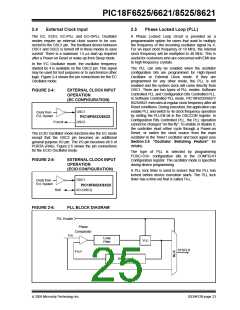
FIGURE 2-6:
PLL BLOCK DIAGRAM
PLL Enable
Phase
Comparator
FIN
Loop
Filter
VCO
SYSCLK
FOUT
Divide by 4
2005 Microchip Technology Inc.
DS39612B-page 23

 MICROCHIP [ MICROCHIP ]