PIC18F6525/6621/8525/8621
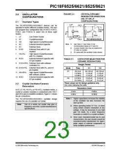
TABLE 2-2:
CAPACITOR SELECTION FOR
CRYSTAL OSCILLATOR
2.3
RC Oscillator
For timing insensitive applications, the “RC” and
“RCIO” device options offer additional cost savings.
The RC oscillator frequency is a function of the supply
voltage, the resistor (REXT) and capacitor (CEXT)
values and the operating temperature. In addition to
this, the oscillator frequency will vary from unit to unit
due to normal process parameter variation. Further-
more, the difference in lead frame capacitance
between package types will also affect the oscillation
frequency, especially for low CEXT values. The user
also needs to take into account variation due to
tolerance of external R and C components used.
Figure 2-3 shows how the R/C combination is
connected.
Ranges Tested:
Mode
Freq
C1
C2
LP
XT
32.0 kHz
200 kHz
1.0 MHz
4.0 MHz
4.0 MHz
8.0 MHz
20.0 MHz
25.0 MHz
33 pF
47-68 pF
15 pF
33 pF
47-68 pF
15 pF
15 pF
15 pF
HS
15 pF
15 pF
15-33 pF
15-33 pF
15-33 pF
15-33 pF
15-33 pF
15-33 pF
These values are for design guidance only.
See notes following this table.
In the RC Oscillator mode, the oscillator frequency
divided by 4 is available on the OSC2 pin. This signal
may be used for test purposes or to synchronize other
logic.
Crystals Used
32 kHz
200 kHz
1 MHz
4 MHz
8 MHz
20 MHz
FIGURE 2-3:
RC OSCILLATOR MODE
VDD
Note 1: Higher capacitance increases the stability
of the oscillator but also increases the
start-up time.
REXT
Internal
OSC1
Clock
CEXT
VSS
2: RS (see Figure 2-1) may be required in
HS mode, as well as XT mode, to avoid
overdriving crystals with low drive level
specification.
PIC18F6X2X/8X2X
OSC2/CLKO
FOSC/4
Recommended values: 3 kΩ ≤ REXT ≤ 100 kΩ
3: Since each resonator/crystal has its own
characteristics, the user should consult the
resonator/crystal manufacturer for appro-
priate values of external components or
verify oscillator performance.
CEXT > 20 pF
The RCIO Oscillator mode functions like the RC mode
except that the OSC2 pin becomes an additional
general purpose I/O pin. The I/O pin becomes bit 6 of
PORTA (RA6).
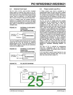
An external clock source may also be connected to the
OSC1 pin in the HS, XT and LP modes as shown in
Figure 2-2.
FIGURE 2-2:
EXTERNAL CLOCK INPUT
OPERATION (HS, XT OR
LP OSCILLATOR
CONFIGURATION)
OSC1
Clock from
Ext. System
PIC18F6X2X/8X2X
OSC2
Open
DS39612B-page 22
2005 Microchip Technology Inc.

 MICROCHIP [ MICROCHIP ]