PIC18F6525/6621/8525/8621
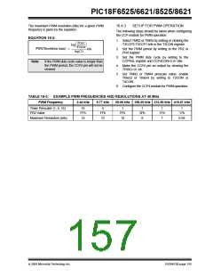
The maximum PWM resolution (bits) for a given PWM
frequency is given by the equation:
16.4.3
SETUP FOR PWM OPERATION
The following steps should be taken when configuring
the CCP module for PWM operation:
EQUATION 16-3:
1. Select TMR2 or TMR4 by setting or clearing the
T3CCP2:T3CCP1 bits in the T3CON register.
FOSC
---------------
log
FPWM
PWM Resolution (max)
= ----------------------------- b i t s
2. Set the PWM period by writing to the PR2 or
PR4 register
log(2)
3. Set the PWM duty cycle by writing to the
CCPR4L register and CCP4CON<5:4> bits.
Note:
If the PWM duty cycle value is longer than
the PWM period, the CCP4 pin will not be
cleared.
4. Make the CCP4 pin an output by clearing the
TRISG<3> bit.
5. Set TMR2 or TMR4 prescale value, enable
Timer2 or Timer4 by writing to T2CON or
T4CON.
6. Configure the CCP4 module for PWM operation.
TABLE 16-3: EXAMPLE PWM FREQUENCIES AND RESOLUTIONS AT 40 MHz
PWM Frequency
2.44 kHz
9.77 kHz
39.06 kHz 156.25 kHz 312.50 kHz 416.67 kHz
Timer Prescaler (1, 4, 16)
PR2 Value
16
FFh
14
4
1
1
3Fh
8
1
1Fh
7
1
FFh
12
FFh
10
17h
6.58
Maximum Resolution (bits)
2005 Microchip Technology Inc.
DS39612B-page 155

 MICROCHIP [ MICROCHIP ]