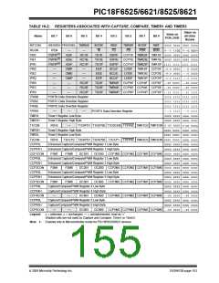
PIC18F6525/6621/8525/8621
16.2.3
SOFTWARE INTERRUPT
16.2 Capture Mode
When the Capture mode is changed, a false capture
interrupt may be generated. The user should keep bit
CCP4IE (PIE3<1>) clear to avoid false interrupts and
should clear the flag bit, CCP4IF, following any such
change in operating mode.
In Capture mode, the CCPR4H:CCPR4L register pair
captures the 16-bit value of the TMR1 or TMR3 regis-
ters when an event occurs on pin RG3/CCP4/P1D. An
event is defined as one of the following:
• every falling edge
• every rising edge
16.2.4
CCP PRESCALER
• every 4th rising edge
• every 16th rising edge
There are four prescaler settings in Capture mode; they
are specified as part of the operating mode selected by
the mode select bits (CCP4M3:CCP4M0). Whenever
the CCP module is turned off or the CCP module is not
in Capture mode, the prescaler counter is cleared. This
means that any Reset will clear the prescaler counter.
The event is selected by the mode select bits,
CCP4M3:CCP4M0 (CCP4CON<3:0>). When
a
capture is made, the interrupt request flag bit CCP4IF
(PIR3<1>) is set; it must be cleared in software. If
another capture occurs before the value in register
CCPR4 is read, the old captured value is overwritten by
the new captured value.
Switching from one capture prescaler to another may
generate an interrupt. Also, the prescaler counter will
not be cleared; therefore, the first capture may be from
a
non-zero prescaler. Example 16-1 shows the
16.2.1
CCP PIN CONFIGURATION
recommended method for switching between capture
prescalers. This example also clears the prescaler
counter and will not generate the “false” interrupt.
In Capture mode, the RG3/CCP4/P1D pin should be
configured as an input by setting the TRISG<3> bit.
Note:
If the RG3/CCP4/P1D is configured as an
output, a write to the port can cause a
capture condition.
EXAMPLE 16-1:
CHANGING BETWEEN
CAPTURE PRESCALERS
CLRF
CCP4CON
; Turn CCP module off
MOVLW NEW_CAPT_PS ; Load WREG with the
; new prescaler mode
16.2.2
TIMER1/TIMER3 MODE SELECTION
The timers that are to be used with the capture feature
(Timer1 and/or Timer3) must be running in Timer mode
or Synchronized Counter mode. In Asynchronous
Counter mode, the capture operation may not work.
The timer to be used with each CCP module is selected
in the T3CON register (see Section 16.1.1 “CCP
Modules and Timer Resources”).
; value and CCP ON
; Load CCP1CON with
; this value
MOVWF CCP4CON
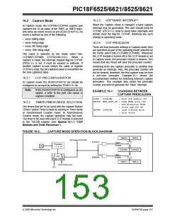
FIGURE 16-2:
CAPTURE MODE OPERATION BLOCK DIAGRAM
TMR3H
TMR3L
CCPR4L
TMR1L
Set Flag bit CCP4IF
T3CCP2
TMR3
Enable
Prescaler
÷ 1, 4, 16
RG3/CCP4/P1D pin
CCPR4H
TMR1
and
Edge Detect
Enable
T3CCP2
TMR1H
CCP1CON<3:0>
Q’s
2005 Microchip Technology Inc.
DS39612B-page 151

 MICROCHIP [ MICROCHIP ]