PIC17C75X
9. The SSP Module shifts in the ACK bit from the
slave device, and writes its value into the
SSPCON2 register ( SSPCON2<6>).
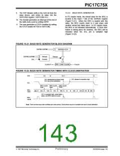
15.2.6 BAUD RATE GENERATOR
2
In I C master mode, the reload value for the BRG is
located in the lower 7 bits of the SSPADD register
(Figure 15-21). When the BRG is loaded with this
value, the BRG counts down to 0 and stops until
another reload has taken place. In I2C master mode,
the BRG is not reloaded automatically. If Clock Arbi-
tration is taking place for instance, the BRG will be
reloaded when the SCL pin is sampled high
(Figure 15-22).
10. The module generates an interrupt at the end of
the ninth clock cycle by setting SSPIF.
11. The user generates a STOP condition by setting
the STOP enable bit PEN in SSPCON2.
FIGURE 15-21: BAUD RATE GENERATOR BLOCK DIAGRAM
SSPM3:SSPM0
SSPADD<6:0>
SSPM3:SSPM0
SCL
Reload
Control
Reload
BRG Down Counter
CLKOUT
Fosc/4
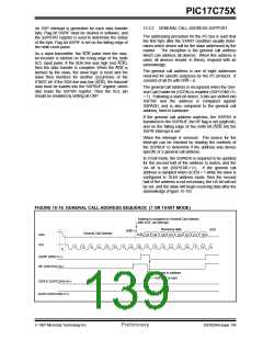
FIGURE 15-22: BAUD RATE GENERATOR TIMING WITH CLOCK ARBITRATION
SDA
DX
DX-1
SCL allowed to transition high
SCL deasserted but slave holds
SCL low (clock arbitration)
SCL
BRG counts
down
BRG counts BRG counts
down
down
BRG
value
00h
03h
02h
01h
00h
XX
03h
02h
01h
00h
SCL is sampled high, reload takes
place, and BRG starts its count.
BRG
reload
Note: There are two baud rate overflows per clock period. Clock period may be of variable time due to clock arbitration.
1997 Microchip Technology Inc.
Preliminary
DS30264A-page 143

 MICROCHIP [ MICROCHIP ]