PIC17C75X
2
15.2.4 MULTI-MASTER MODE
15.2.5.1 I C MASTER MODE OPERATION
In multi-master mode, the interrupt generation on the
detection of the START and STOP conditions allows
the determination of when the bus is free. The STOP
(P) and START (S) bits are cleared from a reset or
The master device generates all of the serial clock
pulses and the START and STOP conditions. A trans-
fer is ended with a STOP condition or with a repeated
START condition. Since the repeated START condi-
tion is also the beginning of the next serial transfer, the
2
when the SSP module is disabled. Control of the I C
2
bus may be taken when bit P (SSPSTAT<4>) is set, or
the bus is idle with both the S and P bits clear. When
the bus is busy, enabling the SSP Interrupt will gener-
ate the interrupt when the STOP condition occurs.
I C bus will not be released.
In Master transmitter mode serial data is output
through SDA, while SCL outputs the serial clock. The
first byte transmitted contains the slave address of the
receiving device, (7 bits) and the data direction bit. In
this case the data direction bit (R/W) will be logic '0'.
Serial data is transmitted 8 bits at a time. After each
byte is transmitted, an acknowledge bit is received.
START and STOP conditions are output to indicate the
beginning and the end of a serial transfer.
In multi-master operation, the SDA line must be moni-
tored to see if the signal level is the expected output
level. This check is performed in hardware, with the
result placed in the BCLIF bit.
The states where arbitration can be lost are:
• Address Transfer
In Master receive mode the first byte transmitted con-
tains the slave address of the transmitting device
(7 bits) and the data direction bit. In this case the data
direction bit (R/W) will be logic '1'. Thus the first byte
transmitted is a 7-bit slave address followed by a '1' to
indicate receive bit. Serial data is received via SDA
while SCL outputs the serial clock. Serial data is
received 8 bits at a time. After each byte is received,
an acknowledge bit is transmitted. START and STOP
conditions indicate the beginning and end of transmis-
sion.
• Data Transfer
• A Start Condition
• A Restart Condition
• An Acknowledge Condition
2
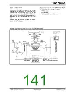
15.2.5 I C MASTER MODE SUPPORT
Master Mode is enabled by setting and clearing the
appropriate SSPM bits in SSPCON1 and by setting
the SSPEN bit. Once master mode is enabled, the
user has six options.
- Assert a start condition on SDA and SCL.
- Assert a restart condition on SDA and SCL.
- Write to the SSPBUF register initiating trans-
mission of data/address.
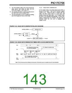
The baud rate generator used for SPI mode operation
is now used to set the SCL clock frequency for either
100 kHz, 400 kHz, or 1 MHz I C operation. The baud
rate generator reload value is contained in the lower 7
bits of the SSPADD register. The baud rate generator
will automatically begin counting on a write to the
SSPBUF. Once the given operation is complete (i.e.
transmission of the last data bit is followed by ACK)
the internal clock will automatically stop counting and
the SCL pin will remain in its last state
2
- Generate a stop Condition on SDA and SCL.
2
- Configure the I C port to receive data.
- Generate an acknowledge condition at the end
of a received byte of data.
2
Note: The SSP Module when configured in I C
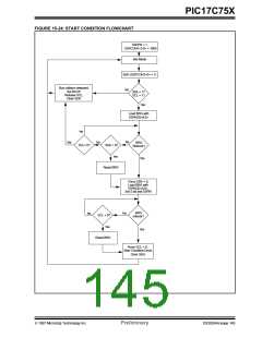
A typical transmit sequence would go as follows:
Master Mode does not allow queueing of
events. For instance: The user is not
allowed to intitiate a start condition, and
immediately write the SSPBUF register to
initate transmission before the START con-
dition is complete. In this case the SSP-
BUF will not be written to, and the WCOL
bit will be set, indicating that a write to the
SSPBUF did not occur.
1. The user generates a Start Condition by setting
the START enable bit (SEN) in SSPCON2.
2. SSPIF is set. The module will wait the required
start time before any other operation takes
place.
3. The user loads the SSPBUF with address to
transmit.
4. Address is shifted out the SDA pin until all 8 bits
are transmitted.
5. The SSP Module shifts in the ACK bit from the
slave device, and writes its value into the
SSPCON2 register ( SSPCON2<6>).
6. The module generates an interrupt at the end of
the ninth clock cycle by setting SSPIF.
7. The user loads the SSPBUF with eight bits of
data.
8. DATA is shifted out the SDA pin until all 8 bits
are transmitted.
DS30264A-page 142
Preliminary
1997 Microchip Technology Inc.

 MICROCHIP [ MICROCHIP ]