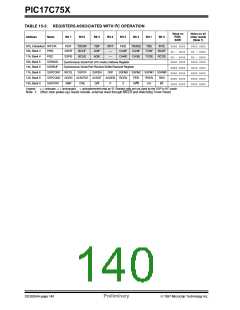
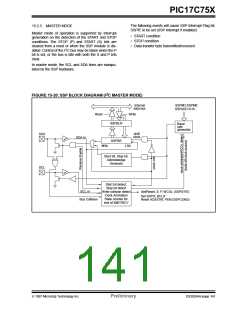
PIC17C75X
2
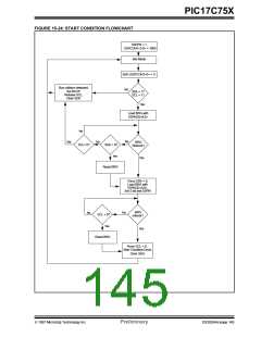
15.2.7 I C MASTER MODE START CONDITION
TIMING
Note: If at the beginning of START condition the
SDA and SCL pins are already sampled
low, or if during the START condition the
SCL line is sampled low before the SDA
line is driven low, a bus collision occurs,
the Bus Collision Interrupt Flag (BCLIF) is
set, the START condition is aborted, and
To initiate a START condition the user sets the start
condition enable bit or SEN bit (SSPCON2<0>). If the
SDA and SCL pins are sampled high, the baud rate
generator is re-loaded with the contents of
SSPADD<6:0>, and starts its count. If SCL and SDA
are both sampled high when the baud rate generator
2
the I C module is reset into its IDLE state.
times out (T
), the SDA pin is driven low. The action
BRG
of the SDA being driven low while SCL is high is the
START condition, and causes the S bit (SSPSTAT<3>)
to be set. Since the I C module is configured in master
mode, a '1' in the S bit causes the SSPIF flag to be
set. Following this, the baud rate generator is reloaded
with the contents of SSPADD<6:0> and resumes its
15.2.7.1 WCOL STATUS FLAG
2
If the user writes the SSPBUF when an START
sequence is in progress, then WCOL is set and the
contents of the buffer are unchanged (the write doesn’t
occur).
count. When the baud rate generator times out (T
)
BRG
Note: Because queueing of events is not
allowed, writing to the lower 5 bits of
SSPCON2 is disabled until the START
condition is complete.
the SEN bit in the SSPCON2 register will be automati-
cally cleared, the baud rate generator is suspended
leaving the SDA line held low, and the START condi-
tion is complete.
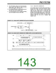
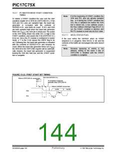
FIGURE 15-23: FIRST START BIT TIMING
Set S bit (SSPSTAT<3>)
Write to SSPCON2<0> occurs here.
SDA = 1,
At completion of start bit,
automatic clear SSPCON2<0>
SCL = 1
TBRG
TBRG
Write to SSPBUF occurs here
2nd Bit
1st Bit
TBRG
SDA
SCL
TBRG
S
DS30264A-page 144
Preliminary
1997 Microchip Technology Inc.

 MICROCHIP [ MICROCHIP ]