PIC17C75X
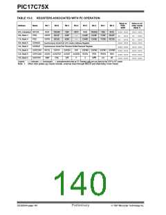
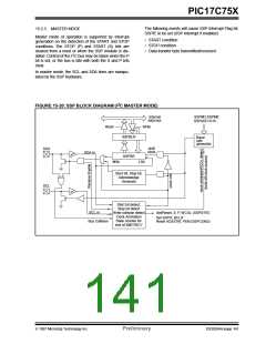
15.2.3 MASTER MODE
The following events will cause SSP Interrupt Flag bit,
SSPIF, to be set (SSP Interrupt if enabled):
Master mode of operation is supported by interrupt
generation on the detection of the START and STOP
conditions. The STOP (P) and START (S) bits are
cleared from a reset or when the SSP module is dis-
• START condition
• STOP condition
• Data transfer byte transmitted/received
2
abled. Control of the I C bus may be taken when the P
bit is set, or the bus is idle with both the S and P bits
clear.
In master mode, the SCL and SDA lines are manipu-
lated by the SSP hardware.
2
FIGURE 15-20: SSP BLOCK DIAGRAM (I C MASTER MODE)
Internal
data bus
SSPM3:SSPM0
SSPADD<6:0>
Read
Write
SSPBUF
SSPSR
Baud
rate
generator
SDA
shift
clock
SDA in
MSb
LSb
Start bit, Stop bit,
Acknowledge
Generate
SCL
Start bit detect,
Stop bit detect
Write collision detect
Clock Arbitration
State counter for
end of XMIT/RCV
SCL in
Bus Collision
Set/Reset, S, P, WCOL (SSPSTAT)
Set SSPIF, BCLIF
Reset ACKSTAT, PEN (SSPCON2)
1997 Microchip Technology Inc.
Preliminary
DS30264A-page 141

 MICROCHIP [ MICROCHIP ]