PIC17C75X
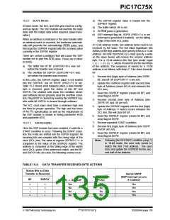
An SSP interrupt is generated for each data transfer
byte. Flag bit SSPIF must be cleared in software, and
the SSPSTAT register is used to determine the status
of the byte. Flag bit SSPIF is set on the falling edge of
the ninth clock pulse.
15.2.2 GENERAL CALL ADDRESS SUPPORT
The addressing procedure for the I2C bus is such that
the first byte after the START condition usually deter-
mines which device will be the slave addressed by the
master. The exception is the general call address
which can address all devices. When this address is
used, all devices should, in theory, respond with an
acknowledge.
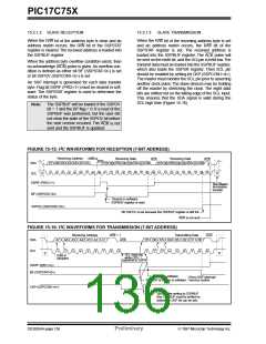
As a slave-transmitter, the ACK pulse from the mas-
ter-receiver is latched on the rising edge of the ninth
SCL input pulse. If the SDA line was high (not ACK),
then the data transfer is complete. When the ACK is
latched by the slave, the slave logic is reset and the
slave then monitors for another occurrence of the
START bit. If the SDA line was low (ACK), the transmit
data must be loaded into the SSPBUF register, which
also loads the SSPSR register. Then the SCL pin
should be enabled by setting bit CKP.
The general call address is one of eight addresses
reserved for specific purposes by the I2C protocol. It
consists of all 0’s with R/W = 0
The general call address is recognized when the Gen-
eral Call Enable bit (GCEN) is enabled (SSPCON2<7>
= 1). Following a start-bit detect, 8-bits are shifted into
SSPSR and the address is compared against
SSPADD, and is also compared to the general call
address, fixed in hardware.
If the general call address matches, the SSPSR is
transfered to the SSPBUF, the BF flag is set (eigth bit),
and on the falling edge of the ninth bit (ACK bit) the
SSPIF interrupt is set.
When the interrupt is serviced. The source for the
interrupt can be checked by reading the contents of
the SSPBUF to determine if the address was device
specific or a general call address.
In 10-bit mode, the SSPADD is required to be updated
for the second half of the address to match, and the
UA bit is set (SSPSTAT<1>). If the general call
address is sampled when GCEN = 1 while the slave is
configured in 10-bit address mode, then the second
half of the address is not necessary, the UA bit will not
be set, and the slave will begin receiving data after the
acknowledge (Figure 15-19).
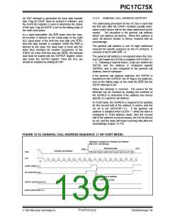
FIGURE 15-19: GENERAL CALL ADDRESS SEQUENCE (7 OR 10-BIT MODE)
Address is compared to General Call Address
after ACK, set interrupt
Receiving data
R/W = 0
ACK
9
General Call Address
ACK
SDA
SCL
D7 D6
D5 D4
D3 D2 D1
D0
8
1
2
3
4
5
6
7
8
9
1
2
3
4
5
6
7
S
SSPIF (PIR2<7>)
BF (SSPSTAT<0>)
Cleared in software
SSPBUF is read
SSPOV (SSPCON1<6>)
GCEN (SSPCON2<7>)
1997 Microchip Technology Inc.
Preliminary
DS30264A-page 139

 MICROCHIP [ MICROCHIP ]