PIC17C75X
2
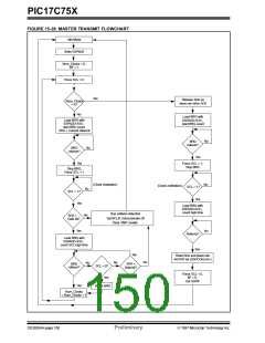
15.2.8 I C MASTER MODE RESTART CONDITION
Immediately following the SSPIF bit getting set, the
user may write the SSPBUF with the 7-bit address in
7-bit mode, or the default first address in 10-bit mode.
After the first eight bits are transmitted and an ACK is
received, the user may then transmit an additional
eight bits of address (10-bit mode) or eight bits of data
(7-bit mode).
TIMING
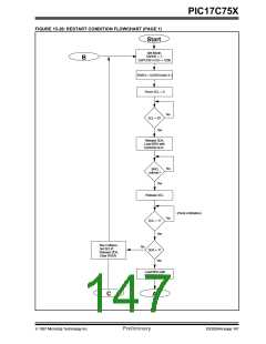
A RESTART condition occurs when the RSEN bit
(SSPCON2<1>) is programmed high and the SSP
module is in the idle state. When the RSEN bit is set,
the SCL pin is asserted low. When the SCL pin is
sampled low, the baud rate generator is loaded with
the contents of SSPADD<5:0>, and begins counting.
The SDA pin is released (brought high) for one baud
After the write to the SSPBUF, each bit of address will
be shifted out on the falling edge of SCL until all seven
address bits and the R/W bit are completed. On the
falling edge of the eighth clock the master will
de-assert the SDA pin allowing the slave to respond
with an acknowledge. On the falling edge of the ninth
clock the master will sample the SDA pin to see if the
address was recognized by a slave. The status of the
ACK bit is programmed into the AKSTAT status bit
SSPCON2<6>. Following the falling edge of the ninth
clock transmission of the address, the SSPIF is set,
the BF flag is cleared, and the baud rate generator is
turned off until another write to the SSPBUF takes
place, holding SCL low and allowing SDA to float.
rate generator count (T
). When the baud rate gen-
BRG
erator times out, if SDA is sampled high, the SCL pin
will be de-asserted (brought high). When SCL is sam-
pled high the baud rate generator is re-loaded with the
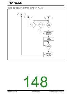
contents of SSPADD<6:0> and begins counting. SDA
and SCL must be sampled high for one T
action is then followed by assertion of the SDA pin
(SDA = 0) for one T while SCL = 1. Following
this, the RSEN bit in the SSPCON2 register will be
automatically cleared, and the baud rate generator is
not reloaded, leaving the SDA pin held low. As soon
as a start condition is detected on the SDA and SCL
pins, the S bit (SSPSTAT<3>) will be set. The SSPIF
bit will not be set until the baud rate generator has
timed-out.
. This
BRG
BRG
15.2.8.1 WCOL STATUS FLAG
If the user writes the SSPBUF when a RESTART
sequence is in progress, then WCOL is set and the
contents of the buffer are unchanged (the write doesn’t
occur).
Note 1: If the RSEN is programmed while a trans-
mit is in progress, it will not take effect.
Note 2: A bus collision during the RESTART con-
Note: Because queueing of events is not
allowed, writing of the lower 5 bits of
SSPCON2 is disabled until the RESTART
condition is complete.
dition occurs if:
•SDA is sampled low when SCL goes
from low to high.
•SCL goes low before SDA is asserted
low. This may indicate that another
master is attempting to transmit a
data "1".
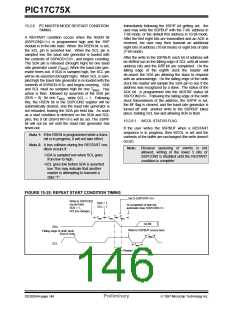
FIGURE 15-25: REPEAT START CONDITION TIMING
Set S (SSPSTAT<3>)
Write to SSPCON2
SDA = 1,
occurs here.
At completion of start bit,
automatic clear SSPCON2<1>
SCL = 1
SDA = 1,
SCL(no change)
TBRG
TBRG
TBRG
1st Bit
SDA
Write to SSPBUF occurs here.
TBRG
Falling edge of ninth clock
End of Xmit
SCL
TBRG
Sr = Restart
DS30264A-page 146
Preliminary
1997 Microchip Technology Inc.

 MICROCHIP [ MICROCHIP ]