PIC17C75X
15.2.1 SLAVE MODE
a) The SSPSR register value is loaded into the
SSPBUF register.
In slave mode, the SCL and SDA pins must be config-
ured as inputs. The SSP module will override the input
state with the output data when required (slave-trans-
mitter).
b) The buffer full bit, BF is set.
c) An ACK pulse is generated.
d) SSP interrupt flag bit, SSPIF (PIR2<7>) is set
(interrupt is generated if enabled) - on the falling
edge of the ninth SCL pulse.
When an address is matched or the data transfer after
an address match is received, the hardware automati-
cally will generate the acknowledge (ACK) pulse, and
then load the SSPBUF register with the received value
currently in the SSPSR register.
In 10-bit address mode, two address bytes need to be
received by the slave. The five Most Significant bits
(MSbs) of the first address byte specify if this is a 10-bit
address. Bit R/W (SSPSTAT<2>) must specify a write
so the slave device will receive the second address
byte. For a 10-bit address the first byte would equal
‘1111 0 A9 A8 0’, where A9 and A8 are the two MSbs
of the address. The sequence of events for a 10-bit
address is as follows, with steps 7- 9 for slave-transmit-
ter:
There are certain conditions that will cause the SSP
module not to give this ACK pulse. These are if either
(or both):
a) The buffer full bit BF (SSPSTAT<0>) was set
before the transfer was received.
b) The overflow bit SSPOV (SSPCON1<6>) was
set before the transfer was received.
1. Receive first (high) byte of Address (bits SSPIF,
BF, and bit UA (SSPSTAT<1>) are set).
In this case, the SSPSR register value is not loaded
into the SSPBUF, but bit SSPIF (PIR2<7>) is set.
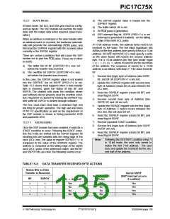
Table 15-2 shows what happens when a data transfer
byte is received, given the status of bits BF and
SSPOV. The shaded cells show the condition where
user software did not properly clear the overflow condi-
tion. Flag bit BF is cleared by reading the SSPBUF reg-
ister while bit SSPOV is cleared through software.
2. Update the SSPADD register with second (low)
byte of Address (clears bit UA and releases the
SCL line).
3. Read the SSPBUF register (clears bit BF) and
clear flag bit SSPIF.
4. Receive second (low) byte of Address (bits
SSPIF, BF, and UA are set).
The SCL clock input must have a minimum high and
low time for proper operation. The high and low times
of the I C specification as well as the requirement of
the SSP module is shown in timing parameter #100
and parameter #101.
5. Update the SSPADD register with the first (high)
byte of Address, if match occurs releases the
SCL line, this will clear bit UA.
2
6. Read the SSPBUF register (clears bit BF) and
clear flag bit SSPIF.
7. Receive repeated START condition.
15.2.1.1 ADDRESSING
8. Receive first (high) byte of Address (bits SSPIF
and BF are set).
Once the SSP module has been enabled, it waits for a
START condition to occur. Following the START condi-
tion, the 8-bits are shifted into the SSPSR register. All
incoming bits are sampled with the rising edge of the
clock (SCL) line. The value of register SSPSR<7:1> is
compared to the value of the SSPADD register. The
address is compared on the falling edge of the eighth
clock (SCL) pulse. If the addresses match, and the BF
and SSPOV bits are clear, the following events occur:
9. Read the SSPBUF register (clears bit BF) and
clear flag bit SSPIF.
Note: Following the RESTART condition (step 7)
in 10-bit mode, the user only needs to
match the first 7-bit address. The user
does not update the SSPADD for the sec-
ond half of the address.
TABLE 15-2: DATA TRANSFER RECEIVED BYTE ACTIONS
Status Bits as Data
Transfer is Received
Set bit SSPIF
(SSP Interrupt occurs
if enabled)
Generate ACK
Pulse
BF
SSPOV
SSPSR → SSPBUF
0
1
1
0
0
0
1
1
Yes
No
No
No
Yes
No
No
No
Yes
Yes
Yes
Yes
1997 Microchip Technology Inc.
Preliminary
DS30264A-page 135

 MICROCHIP [ MICROCHIP ]