PIC16F913/914/916/917/946
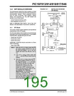
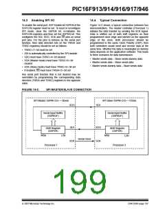
FIGURE 14-1:
SSP BLOCK DIAGRAM
(SPI MODE)
14.0 SSP MODULE OVERVIEW
The Synchronous Serial Port (SSP) module is a serial
interface used to communicate with other peripheral or
microcontroller devices. These peripheral devices
may be serial EEPROMs, shift registers, display
drivers, A/D converters, etc. The SSP module can
operate in one of two modes:
Internal
Data Bus
Read
Write
SSPBUF Reg
• Serial Peripheral Interface (SPI)
• Inter-Integrated Circuit (I2C™)
Refer to Application Note AN578, “Use of the SSP
Module in the Multi-Master Environment” (DS00578).
SSPSR Reg
SDI/SDA
SDO
Shift
Clock
bit 0
14.1 SPI Mode
Peripheral OE
This section contains register definitions and operational
characteristics of the SPI module.
Control
Enable
SS
The SPI mode allows 8 bits of data to be synchronously
transmitted and received simultaneously. To accomplish
communication, typically three pins are used:
SS
Edge
Select
• Serial Data Out (SDO)
• Serial Data In (SDI)
• Serial Clock (SCK)
2
Clock Select
Additionally, a fourth pin may be used when in a Slave
mode of operation:
SSPM<3:0>
4
TMR2 Output
2
• Slave Select (SS)
Edge
Note 1: When the SPI is in Slave mode with SS
pin control enabled (SSPM<3:0> bits of
the SSPCON register = 0100), the SPI
module will reset if the SS pin is set to
VDD.
Select
TCY
Prescaler
4, 16, 64
SCK/
SCL
TRISC<6>
2: If the SPI is used in Slave mode with
CKE = 1, then the SS pin control must be
enabled.
3: When the SPI is in Slave mode with SS
pin control enabled (SSPM<3:0> bits of
the SSPCON register = 0100), the state
of the SS pin can affect the state read
back from the TRISC<4> bit. The
peripheral OE signal from the SSP
module into PORTC controls the state
that is read back from the TRISC<4> bit
(see Section 19.0 “Electrical
Specifications” for information on
PORTC). If read-write-modify
instructions, such as BSF,are performed
on the TRISC register while the SS pin is
high, this will cause the TRISC<4> bit to
be set, thus disabling the SDO output.
© 2007 Microchip Technology Inc.
DS41250F-page 193

 MICROCHIP [ MICROCHIP ]