PIC16F716
When enabling peripheral functions, care should be
taken in defining TRIS bits for each PORTB pin. Some
peripherals override the TRIS bit to make a pin an
output, while other peripherals override the TRIS bit to
make a pin an input. Since the TRIS bit override is in
effect while the peripheral is enabled, read-modify-
write instructions (such as BSF, BCF, XORWF) with
TRISB as the destination should be avoided. The user
should refer to the corresponding peripheral section for
the correct TRIS bit settings.
3.2
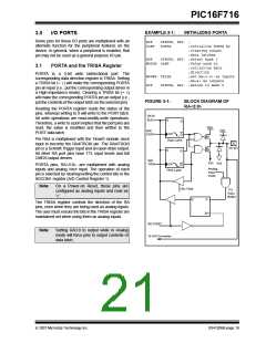
PORTB and the TRISB Register
PORTB is an 8-bit wide bidirectional port. The
corresponding data direction register is TRISB. Setting
a TRISB bit (= 1) will make the corresponding PORTB
pin an input (i.e., put the corresponding output driver in
a High-Impedance mode). Clearing a TRISB bit (= 0)
will make the corresponding PORTB pin an output (i.e.,
put the contents of the output latch on the selected pin).
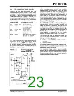
EXAMPLE 3-2:
INITIALIZING PORTB
Four of PORTB’s pins, RB<7:4>, have an interrupt-on-
change feature. Only pins configured as inputs can
cause this interrupt to occur (i.e., any RB<7:4> pin
configured as an output is excluded from the interrupt-
on-change comparison). The input pins, RB<7:4>, are
compared with the old value latched on the last read of
PORTB. The “mismatch” outputs of RB<7:4> are
OR’ed together to generate the RB Port Change
Interrupt with flag bit RBIF of the INTCON register.
BCF
CLRF
STATUS, RP0
;select Bank 0
PORTB
;Initialize PORTB by
;clearing output
;data latches
BSF
MOVLW
STATUS, RP0
0xCF
;Select Bank 1
;Value used to
;initialize data
;direction
MOVWF
TRISB
;Set RB<3:0> as inputs
;RB<5:4> as outputs
;RB<7:6> as inputs
This interrupt can wake the device from Sleep. The
user, in the Interrupt Service Routine, can clear the
interrupt in the following manner:
1. Perform a read of PORTB to end the mismatch
condition.
Each of the PORTB pins has a weak internal pull-up. A
single control bit can turn on all the pull-ups. This is
performed by clearing bit RBPU of the OPTION regis-
ter. The weak pull-up is automatically turned off when
the port pin is configured as an output. The pull-ups are
disabled on a Power-on Reset.
2. Clear flag bit RBIF.
A mismatch condition will continue to set flag bit RBIF.
Reading PORTB will end the mismatch condition and
allow flag bit RBIF to be cleared.
The interrupt-on-change feature is recommended for
wake-up on key depression operation and operations
where PORTB is only used for the interrupt-on-change
feature. Polling of PORTB is not recommended while
using the interrupt-on-change feature.
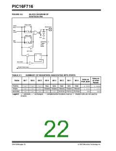
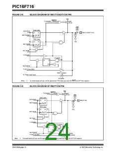
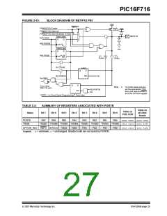
FIGURE 3-3:
BLOCK DIAGRAM OF
RB0/INT/ECCPAS2 PIN
VDD
VDD
RBPU(1)
weak
pull-up
P
Data Latch
DATA
BUS
D
Q
RB0/
INT/
ECCPAS2
WR
PORT
CK
TRIS Latch
D
Q
VSS
WR
CK
TRIS
TTL
Input
Buffer
RD TRIS
Q
D
EN
RD PORT
Schmitt Trigger
Buffer
RB0/INT
RD PORT
ECCPAS2: ECCP Auto-shutdown input
Note 1:
To enable weak pull-ups, set the appropriate TRIS
bit(s) and clear the RBPU bit (OPTION register).
© 2007 Microchip Technology Inc.
DS41206B-page 21

 MICROCHIP [ MICROCHIP ]