PIC16F/LF1946/47
24.1.1.5
TSR Status
24.1.1.7
Asynchronous Transmission Set-up:
The TRMT bit of the TXxSTA register indicates the
status of the TSR register. This is a read-only bit. The
TRMT bit is set when the TSR register is empty and is
cleared when a character is transferred to the TSR
register from the TXxREG. The TRMT bit remains clear
until all bits have been shifted out of the TSR register.
No interrupt logic is tied to this bit, so the user needs to
poll this bit to determine the TSR status.
1. Initialize the SPxBRGH:SPxBRGL register pair
and the BRGH and BRG16 bits to achieve the
desired baud rate (see Section 24.3 “EUSART
Baud Rate Generator (BRG)”).
2. Set the RXx/DTx and TXx/CKx TRIS controls to
‘1’.
3. Enable the asynchronous serial port by clearing
the SYNC bit and setting the SPEN bit.
Note:
The TSR register is not mapped in data
memory, so it is not available to the user.
4. If 9-bit transmission is desired, set the TX9
control bit. A set ninth data bit will indicate that
the 8 Least Significant data bits are an address
when the receiver is set for address detection.
24.1.1.6
Transmitting 9-Bit Characters
The EUSART supports 9-bit character transmissions.
When the TX9 bit of the TXxSTA register is set the
EUSART will shift 9 bits out for each character transmit-
ted. The TX9D bit of the TXxSTA register is the ninth,
and Most Significant, data bit. When transmitting 9-bit
data, the TX9D data bit must be written before writing
the 8 Least Significant bits into the TXxREG. All nine
bits of data will be transferred to the TSR shift register
immediately after the TXxREG is written.
5. Set the CKTXP control bit if inverted transmit
data polarity is desired.
6. Enable the transmission by setting the TXEN
control bit. This will cause the TXxIF interrupt bit
to be set.
7. If interrupts are desired, set the TXxIE interrupt
enable bit. An interrupt will occur immediately
provided that the GIE and PEIE bits of the
INTCON register are also set.
A special 9-bit Address mode is available for use with
multiple receivers. See Section 24.1.2.8 “Address
Detection” for more information on the Address mode.
8. If 9-bit transmission is selected, the ninth bit
should be loaded into the TX9D data bit.
9. Load 8-bit data into the TXxREG register. This
will start the transmission.
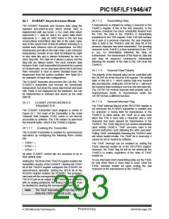
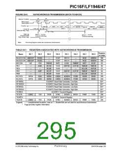
FIGURE 24-3:
ASYNCHRONOUS TRANSMISSION
Write to TXxREG
Word 1
BRG Output
(Shift Clock)
TXx/CKx pin
Start bit
bit 0
bit 1
Word 1
bit 7/8
Stop bit
TXxIF bit
(Transmit Buffer
Reg. Empty Flag)
1 TCY
Word 1
Transmit Shift Reg
TRMT bit
(Transmit Shift
Reg. Empty Flag)
DS41414A-page 292
Preliminary
2010 Microchip Technology Inc.

 MICROCHIP [ MICROCHIP ]