PIC16F/LF1946/47
24.1.2.9
Asynchronous Reception Set-up:
24.1.2.10 9-bit Address Detection Mode Set-up
1. Initialize the SPxBRGH:SPxBRGL register pair
and the BRGH and BRG16 bits to achieve the
desired baud rate (see Section 24.3 “EUSART
Baud Rate Generator (BRG)”).
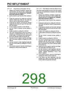
This mode would typically be used in RS-485 systems.
To set up an Asynchronous Reception with Address
Detect Enable:
1. Initialize the SPxBRGH, SPxBRGL register pair
and the BRGH and BRG16 bits to achieve the
desired baud rate (see Section 24.3 “EUSART
Baud Rate Generator (BRG)”).
2. Set the RXx/DTx and TXx/CKx TRIS controls to
‘1’.
3. Enable the serial port by setting the SPEN bit
and the RXx/DTx pin TRIS bit. The SYNC bit
must be clear for asynchronous operation.
2. Set the RXx/DTx and TXx/CKx TRIS controls to
‘1’.
4. If interrupts are desired, set the RCxIE interrupt
enable bit and set the GIE and PEIE bits of the
INTCON register.
3. Enable the serial port by setting the SPEN bit.
The SYNC bit must be clear for asynchronous
operation.
5. If 9-bit reception is desired, set the RX9 bit.
4. If interrupts are desired, set the RCxIE interrupt
enable bit and set the GIE and PEIE bits of the
INTCON register.
6. Set the DTRXP if inverted receive polarity is
desired.
7. Enable reception by setting the CREN bit.
5. Enable 9-bit reception by setting the RX9 bit.
8. The RCxIF interrupt flag bit will be set when a
character is transferred from the RSR to the
receive buffer. An interrupt will be generated if
the RCxIE interrupt enable bit was also set.
6. Enable address detection by setting the ADDEN
bit.
7. Set the DTRXP if inverted receive polarity is
desired.
9. Read the RCxSTA register to get the error flags
and, if 9-bit data reception is enabled, the ninth
data bit.
8. Enable reception by setting the CREN bit.
9. The RCxIF interrupt flag bit will be set when a
character with the ninth bit set is transferred
from the RSR to the receive buffer. An interrupt
will be generated if the RCxIE interrupt enable
bit was also set.
10. Get the received 8 Least Significant data bits
from the receive buffer by reading the RCxREG
register.
11. If an overrun occurred, clear the OERR flag by
clearing the CREN receiver enable bit.
10. Read the RCxSTA register to get the error flags.
The ninth data bit will always be set.
11. Get the received 8 Least Significant data bits
from the receive buffer by reading the RCxREG
register. Software determines if this is the
device’s address.
12. If an overrun occurred, clear the OERR flag by
clearing the CREN receiver enable bit.
13. If the device has been addressed, clear the
ADDEN bit to allow all received data into the
receive buffer and generate interrupts.
DS41414A-page 296
Preliminary
2010 Microchip Technology Inc.

 MICROCHIP [ MICROCHIP ]