PIC16F/LF1946/47
24.1.1.2
Transmitting Data
24.1 EUSART Asynchronous Mode
A transmission is initiated by writing a character to the
TXxREG register. If this is the first character, or the
previous character has been completely flushed from
the TSR, the data in the TXxREG is immediately
transferred to the TSR register. If the TSR still contains
all or part of a previous character, the new character
data is held in the TXxREG until the Stop bit of the
previous character has been transmitted. The pending
character in the TXxREG is then transferred to the TSR
in one TCY immediately following the Stop bit
transmission. The transmission of the Start bit, data bits
and Stop bit sequence commences immediately
following the transfer of the data to the TSR from the
TXxREG.
The EUSART transmits and receives data using the
standard non-return-to-zero (NRZ) format. NRZ is
implemented with two levels: a VOH mark state which
represents a ‘1’ data bit, and a VOL space state which
represents a ‘0’ data bit. NRZ refers to the fact that
consecutively transmitted data bits of the same value
stay at the output level of that bit without returning to a
neutral level between each bit transmission. An NRZ
transmission port idles in the mark state. Each character
transmission consists of one Start bit followed by eight
or nine data bits and is always terminated by one or
more Stop bits. The Start bit is always a space and the
Stop bits are always marks. The most common data
format is 8 bits. Each transmitted bit persists for a period
of 1/(Baud Rate). An on-chip dedicated 8-bit/16-bit Baud
Rate Generator is used to derive standard baud rate
frequencies from the system oscillator. See Table 24-5
for examples of baud rate configurations.
24.1.1.3
Transmit Data Polarity
The polarity of the transmit data can be controlled with
the CKTXP bit of the BAUDxCON register. The default
state of this bit is ‘0’ which selects high true transmit
idle and data bits. Setting the CKTXP bit to ‘1’ will invert
the transmit data resulting in low true idle and data bits.
The CKTXP bit controls transmit data polarity only in
Asynchronous mode. In Synchronous mode the
CKTXP bit has a different function.
The EUSART transmits and receives the LSb first. The
EUSART’s transmitter and receiver are functionally
independent, but share the same data format and baud
rate. Parity is not supported by the hardware, but can
be implemented in software and stored as the ninth
data bit.
24.1.1.4
Transmit Interrupt Flag
24.1.1
EUSART ASYNCHRONOUS
TRANSMITTER
The TXxIF interrupt flag bit of the PIR1/PIR3 register is
set whenever the EUSART transmitter is enabled and
no character is being held for transmission in the
TXxREG. In other words, the TXxIF bit is only clear
when the TSR is busy with a character and a new
character has been queued for transmission in the
TXxREG. The TXxIF flag bit is not cleared immediately
upon writing TXxREG. TXxIF becomes valid in the
second instruction cycle following the write execution.
Polling TXxIF immediately following the TXxREG write
will return invalid results. The TXxIF bit is read-only, it
cannot be set or cleared by software.
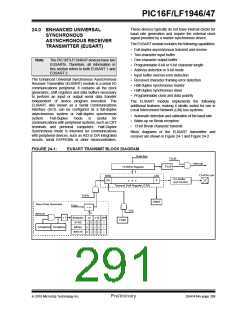
The EUSART transmitter block diagram is shown in
Figure 24-1. The heart of the transmitter is the serial
Transmit Shift Register (TSR), which is not directly
accessible by software. The TSR obtains its data from
the transmit buffer, which is the TXxREG register.
24.1.1.1
Enabling the Transmitter
The EUSART transmitter is enabled for asynchronous
operations by configuring the following three control
bits:
• TXEN = 1
• SYNC = 0
• SPEN = 1
The TXxIF interrupt can be enabled by setting the
TXxIE interrupt enable bit of the PIE1/PIE3 register.
However, the TXxIF flag bit will be set whenever the
TXxREG is empty, regardless of the state of TXxIE
enable bit.
All other EUSART control bits are assumed to be in
their default state.
To use interrupts when transmitting data, set the TXxIE
bit only when there is more data to send. Clear the
TXxIE interrupt enable bit upon writing the last
character of the transmission to the TXxREG.
Setting the TXEN bit of the TXxSTA register enables the
transmitter circuitry of the EUSART. Clearing the SYNC
bit of the TXxSTA register configures the EUSART for
asynchronous operation. Setting the SPEN bit of the
RCxSTA register enables the EUSART. The program-
mer must set the corresponding TRIS bit to configure the
TX/CK I/O pin as an output. If the TXx/CKx pin is shared
with an analog peripheral, the analog I/O function must
be disabled by clearing the corresponding ANSEL bit.
Note:
The TXxIF transmitter interrupt flag is set
when the TXEN enable bit is set.
2010 Microchip Technology Inc.
Preliminary
DS41414A-page 291

 MICROCHIP [ MICROCHIP ]