PIC16F/LF1946/47
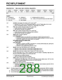
REGISTER 23-5: SSPxMSK: SSPx MASK REGISTER
R/W-1/1
R/W-1/1
R/W-1/1
R/W-1/1
R/W-1/1
R/W-1/1
R/W-1/1
R/W-1/1
MSK<7:0>
bit 7
bit 0
Legend:
R = Readable bit
W = Writable bit
U = Unimplemented bit, read as ‘0’
-n/n = Value at POR and BOR/Value at all other Resets
u = Bit is unchanged
‘1’ = Bit is set
x = Bit is unknown
‘0’ = Bit is cleared
bit 7-1
bit 0
MSK<7:1>: Mask bits
1= The received address bit n is compared to SSPxADD<n> to detect I2C address match
0= The received address bit n is not used to detect I2C address match
MSK<0>: Mask bit for I2C Slave mode, 10-bit Address
I2C Slave mode, 10-bit address (SSPxM<3:0> = 0111or 1111):
1= The received address bit 0 is compared to SSPxADD<0> to detect I2C address match
0= The received address bit 0 is not used to detect I2C address match
I2C Slave mode, 7-bit address, the bit is ignored
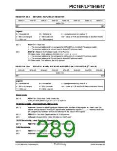
REGISTER 23-6: SSPxADD: MSSPx ADDRESS AND BAUD RATE REGISTER (I2C MODE)
R/W-0/0
R/W-0/0
R/W-0/0
R/W-0/0
R/W-0/0
R/W-0/0
R/W-0/0
R/W-0/0
ADD<7:0>
bit 7
bit 0
Legend:
R = Readable bit
W = Writable bit
U = Unimplemented bit, read as ‘0’
-n/n = Value at POR and BOR/Value at all other Resets
u = Bit is unchanged
‘1’ = Bit is set
x = Bit is unknown
‘0’ = Bit is cleared
Master mode:
bit 7-0
ADD<7:0>: Baud Rate Clock Divider bits
SCLx pin clock period = ((ADD<7:0> + 1) *4)/FOSC
10-Bit Slave mode – Most Significant Address byte:
bit 7-3
Not used: Unused for Most Significant Address byte. Bit state of this register is a “don’t care”. Bit
pattern sent by master is fixed by I2C specification and must be equal to ‘11110’. However, those bits
are compared by hardware and are not affected by the value in this register.
bit 2-1
bit 0
ADD<2:1>: Two Most Significant bits of 10-bit address
Not used: Unused in this mode. Bit state is a “don’t care”.
10-Bit Slave mode – Least Significant Address byte:
bit 7-0
ADD<7:0>: Eight Least Significant bits of 10-bit address
7-Bit Slave mode:
bit 7-1
bit 0
ADD<7:1>: 7-bit address
Not used: Unused in this mode. Bit state is a “don’t care”.
2010 Microchip Technology Inc.
Preliminary
DS41414A-page 287

 MICROCHIP [ MICROCHIP ]