PIC16F/LF1946/47
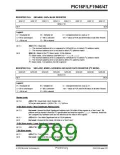
REGISTER 23-3: SSPxCON2: SSPx CONTROL REGISTER 2
R/W-0/0
GCEN
R-0/0
R/W-0/0
ACKDT
R/S/HS-0/0 R/S/HS-0/0
ACKEN RCEN
R/S/HS-0/0
PEN
R/S/HS-0/0 R/W/HS-0/0
RSEN SEN
bit 0
ACKSTAT
bit 7
Legend:
R = Readable bit
W = Writable bit
U = Unimplemented bit, read as ‘0’
u = Bit is unchanged
‘1’ = Bit is set
x = Bit is unknown
‘0’ = Bit is cleared
-n/n = Value at POR and BOR/Value at all other Resets
HC = Cleared by hardware S = User set
bit 7
bit 6
bit 5
GCEN: General Call Enable bit (in I2C Slave mode only)
1= Enable interrupt when a general call address (0x00 or 00h) is received in the SSPxSR
0= General call address disabled
ACKSTAT: Acknowledge Status bit (in I2C mode only)
1= Acknowledge was not received
0= Acknowledge was received
ACKDT: Acknowledge Data bit (in I2C mode only)
In Receive mode:
Value transmitted when the user initiates an Acknowledge sequence at the end of a receive
1= Not Acknowledge
0= Acknowledge
bit 4
ACKEN: Acknowledge Sequence Enable bit (in I2C Master mode only)
In Master Receive mode:
1= Initiate Acknowledge sequence on SDAx and SCLx pins, and transmit ACKDT data bit.
Automatically cleared by hardware.
0= Acknowledge sequence idle
bit 3
bit 2
RCEN: Receive Enable bit (in I2C Master mode only)
1= Enables Receive mode for I2C
0= Receive idle
PEN: Stop Condition Enable bit (in I2C Master mode only)
SCKx Release Control:
1= Initiate Stop condition on SDAx and SCLx pins. Automatically cleared by hardware.
0= Stop condition Idle
bit 1
bit 0
RSEN: Repeated Start Condition Enabled bit (in I2C Master mode only)
1= Initiate Repeated Start condition on SDAx and SCLx pins. Automatically cleared by hardware.
0= Repeated Start condition Idle
SEN: Start Condition Enabled bit (in I2C Master mode only)
In Master mode:
1= Initiate Start condition on SDAx and SCLx pins. Automatically cleared by hardware.
0= Start condition Idle
In Slave mode:
1= Clock stretching is enabled for both slave transmit and slave receive (stretch enabled)
0= Clock stretching is disabled
Note 1: For bits ACKEN, RCEN, PEN, RSEN, SEN: If the I2C module is not in the Idle mode, this bit may not be
set (no spooling) and the SSPxBUF may not be written (or writes to the SSPxBUF are disabled).
2010 Microchip Technology Inc.
Preliminary
DS41414A-page 285

 MICROCHIP [ MICROCHIP ]