PIC16F/LF1946/47
22.1.2
TIMER1 MODE RESOURCE
22.1 Capture Mode
Timer1 must be running in Timer mode or Synchronized
Counter mode for the CCP module to use the capture
feature. In Asynchronous Counter mode, the capture
operation may not work.
The Capture mode function described in this section is
available and identical for CCP modules ECCP1,
ECCP2, ECCP3, CCP4 and CCP5.
Capture mode makes use of the 16-bit Timer1
resource. When an event occurs on the CCPx pin, the
16-bit CCPRxH:CCPRxL register pair captures and
stores the 16-bit value of the TMR1H:TMR1L register
pair, respectively. An event is defined as one of the
following and is configured by the CCPxM<3:0> bits of
the CCPxCON register:
See Section 20.0 “Timer1 Module with Gate Control”
for more information on configuring Timer1.
22.1.3
SOFTWARE INTERRUPT MODE
When the Capture mode is changed, a false capture
interrupt may be generated. The user should keep the
CCPxIE interrupt enable bit of the PIEx register clear to
avoid false interrupts. Additionally, the user should
clear the CCPxIF interrupt flag bit of the PIRx register
following any change in Operating mode.
• Every falling edge
• Every rising edge
• Every 4th rising edge
• Every 16th rising edge
Note:
Clocking Timer1 from the system clock
(FOSC) should not be used in Capture
mode. In order for Capture mode to
recognize the trigger event on the CCPx
pin, Timer1 must be clocked from the
instruction clock (FOSC/4) or from an
external clock source.
When a capture is made, the Interrupt Request Flag bit
CCPxIF of the PIRx register is set. The interrupt flag
must be cleared in software. If another capture occurs
before the value in the CCPRxH, CCPRxL register pair
is read, the old captured value is overwritten by the new
captured value.
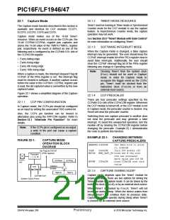
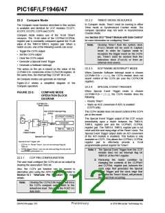
Figure 22-1 shows a simplified diagram of the Capture
operation.
22.1.4
CCP PRESCALER
There are four prescaler settings specified by the
CCPxM<3:0> bits of the CCPxCON register. Whenever
the CCP module is turned off, or the CCP module is not
in Capture mode, the prescaler counter is cleared. Any
Reset will clear the prescaler counter.
22.1.1
CCP PIN CONFIGURATION
In Capture mode, the CCPx pin should be configured
as an input by setting the associated TRIS control bit.
Also, the CCPx pin function can be moved to
alternative pins using the APFCON register. Refer to
Section 12.1 “Alternate Pin Function” for more
details.
Switching from one capture prescaler to another does
not clear the prescaler and may generate a false
interrupt. To avoid this unexpected operation, turn the
module off by clearing the CCPxCON register before
changing the prescaler. Example 22-1 demonstrates
the code to perform this function.
Note:
If the CCPx pin is configured as an output,
a write to the port can cause a capture
condition.
EXAMPLE 22-1:
CHANGING BETWEEN
CAPTURE PRESCALERS
FIGURE 22-1:
CAPTURE MODE
OPERATION BLOCK
DIAGRAM
BANKSELCCPxCON
;Set Bank bits to point
;to CCPxCON
CLRF
MOVLW
CCPxCON
;Turn CCP module off
Set Flag bit CCPxIF
(PIRx register)
NEW_CAPT_PS;Load the W reg with
;the new prescaler
Prescaler
1, 4, 16
;move value and CCP ON
;Load CCPxCON with this
;value
CCPx
pin
CCPRxH
CCPRxL
MOVWF
CCPxCON
Capture
Enable
and
Edge Detect
22.1.5
CAPTURE DURING SLEEP
TMR1H
TMR1L
Capture mode depends upon the Timer1 module for
proper operation. There are two options for driving the
Timer1 module in Capture mode. It can be driven by the
instruction clock (FOSC/4), or by an external clock source.
CCPxM<3:0>
System Clock (FOSC)
When Timer1 is clocked by FOSC/4, Timer1 will not
increment during Sleep. When the device wakes from
Sleep, Timer1 will continue from its previous state.
Capture mode will operate during Sleep when Timer1
is clocked by an external clock source.
DS41414A-page 208
Preliminary
2010 Microchip Technology Inc.

 MICROCHIP [ MICROCHIP ]