PIC16F/LF1946/47
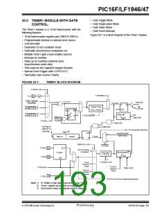
20.1 Timer1 Operation
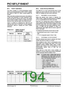
20.2 Clock Source Selection
The Timer1 module is a 16-bit incrementing counter
which is accessed through the TMR1H:TMR1L register
pair. Writes to TMR1H or TMR1L directly update the
counter.
The TMR1CS<1:0> and T1OSCEN bits of the T1CON
register are used to select the clock source for Timer1.
Table 20-2 displays the clock source selections.
20.2.1
INTERNAL CLOCK SOURCE
When used with an internal clock source, the module is
a timer and increments on every instruction cycle.
When used with an external clock source, the module
can be used as either a timer or counter and incre-
ments on every selected edge of the external source.
When the internal clock source is selected, the
TMR1H:TMR1L register pair will increment on multiples
of FOSC as determined by the Timer1 prescaler.
When the FOSC internal clock source is selected, the
Timer1 register value will increment by four counts every
instruction clock cycle. Due to this condition, a 2 LSB
error in resolution will occur when reading the Timer1
value. To utilize the full resolution of Timer1, an
asynchronous input signal must be used to gate the
Timer1 clock input.
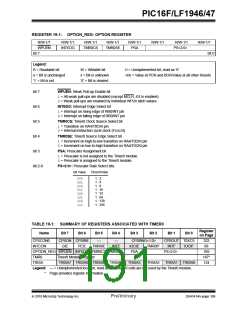
Timer1 is enabled by configuring the TMR1ON and
TMR1GE bits in the T1CON and T1GCON registers,
respectively. Table 20-1 displays the Timer1 enable
selections.
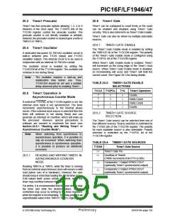
TABLE 20-1: TIMER1 ENABLE
SELECTIONS
The following asynchronous sources may be used:
• Asynchronous event on the T1G pin to Timer1
Gate
Timer1
Operation
TMR1ON
TMR1GE
• C1 or C2 comparator input to Timer1 Gate
0
0
1
1
0
1
0
1
Off
Off
20.2.2
EXTERNAL CLOCK SOURCE
When the external clock source is selected, the Timer1
module may work as a timer or a counter.
Always On
Count Enabled
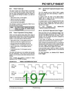
When enabled to count, Timer1 is incremented on the
rising edge of the external clock input T1CKI or the
capacitive sensing oscillator signal. Either of these
external clock sources can be synchronized to the
microcontroller system clock or they can run
asynchronously.
When used as a timer with a clock oscillator, an
external 32.768 kHz crystal can be used in conjunction
with the dedicated internal oscillator circuit.
Note:
In Counter mode, a falling edge must be
registered by the counter prior to the first
incrementing rising edge after any one or
more of the following conditions:
• Timer1 enabled after POR
• Write to TMR1H or TMR1L
• Timer1 is disabled
• Timer1 is disabled (TMR1ON = 0)
when T1CKI is high then Timer1 is
enabled (TMR1ON=1) when T1CKI is
low.
TABLE 20-2: CLOCK SOURCE SELECTIONS
TMR1CS1
TMR1CS0
T1OSCEN
Clock Source
0
0
1
1
1
1
0
1
0
0
x
x
x
0
1
System Clock (FOSC)
Instruction Clock (FOSC/4)
Capacitive Sensing Oscillator
External Clocking on T1CKI Pin
Osc.Circuit On T1OSI/T1OSO Pins
DS41414A-page 192
Preliminary
2010 Microchip Technology Inc.

 MICROCHIP [ MICROCHIP ]