PIC16F/LF1946/47
20.6.2.1
T1G Pin Gate Operation
20.6.4
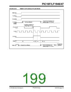
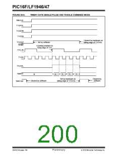
TIMER1 GATE SINGLE-PULSE
MODE
The T1G pin is one source for Timer1 Gate Control. It
can be used to supply an external source to the Timer1
Gate circuitry.
When Timer1 Gate Single-Pulse mode is enabled, it is
possible to capture a single pulse gate event. Timer1
Gate Single-Pulse mode is first enabled by setting the
T1GSPM bit in the T1GCON register. Next, the
T1GGO/DONE bit in the T1GCON register must be set.
The Timer1 will be fully enabled on the next
incrementing edge. On the next trailing edge of the
pulse, the T1GGO/DONE bit will automatically be
cleared. No other gate events will be allowed to
increment Timer1 until the T1GGO/DONE bit is once
again set in software.
20.6.2.2
Timer0 Overflow Gate Operation
When Timer0 increments from FFh to 00h,
low-to-high pulse will automatically be generated and
internally supplied to the Timer1 Gate circuitry.
a
20.6.2.3
Comparator C1 Gate Operation
The output resulting from a Comparator 1 operation can
be selected as a source for Timer1 Gate Control. The
Clearing the T1GSPM bit of the T1GCON register will
also clear the T1GGO/DONE bit. See Figure 20-5 for
timing details.
Comparator
1
output (SYNCC1OUT) can be
synchronized to the Timer1 clock or left asynchronous.
For more information see Section 17.4.1 “Comparator
Output Synchronization”.
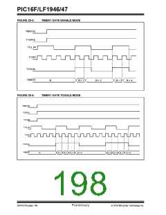
Enabling the Toggle mode and the Single-Pulse mode
simultaneously will permit both sections to work
together. This allows the cycle times on the Timer1
Gate source to be measured. See Figure 20-6 for
timing details.
20.6.2.4
Comparator C2 Gate Operation
The output resulting from a Comparator 2 operation
can be selected as a source for Timer1 Gate Control.
The Comparator 2 output (SYNCC2OUT) can be
synchronized to the Timer1 clock or left asynchronous.
For more information see Section 17.4.1 “Comparator
Output Synchronization”.
20.6.5
TIMER1 GATE VALUE STATUS
When Timer1 Gate Value Status is utilized, it is possible
to read the most current level of the gate control value.
The value is stored in the T1GVAL bit in the T1GCON
register. The T1GVAL bit is valid even when the Timer1
Gate is not enabled (TMR1GE bit is cleared).
20.6.3
TIMER1 GATE TOGGLE MODE
When Timer1 Gate Toggle mode is enabled, it is possi-
ble to measure the full-cycle length of a Timer1 gate
signal, as opposed to the duration of a single level
pulse.
20.6.6
TIMER1 GATE EVENT INTERRUPT
When Timer1 Gate Event Interrupt is enabled, it is pos-
sible to generate an interrupt upon the completion of a
gate event. When the falling edge of T1GVAL occurs,
the TMR1GIF flag bit in the PIR1 register will be set. If
the TMR1GIE bit in the PIE1 register is set, then an
interrupt will be recognized.
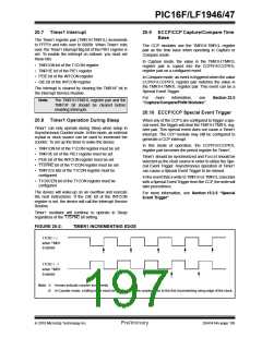
The Timer1 Gate source is routed through a flip-flop
that changes state on every incrementing edge of the
signal. See Figure 20-4 for timing details.
Timer1 Gate Toggle mode is enabled by setting the
T1GTM bit of the T1GCON register. When the T1GTM
bit is cleared, the flip-flop is cleared and held clear. This
is necessary in order to control which edge is
measured.
The TMR1GIF flag bit operates even when the Timer1
Gate is not enabled (TMR1GE bit is cleared).
Note:
Enabling Toggle mode at the same time as
changing the gate polarity may result in
indeterminate operation.
DS41414A-page 194
Preliminary
2010 Microchip Technology Inc.

 MICROCHIP [ MICROCHIP ]