PIC16F/LF1946/47
19.1.3
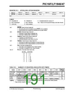
SOFTWARE PROGRAMMABLE
PRESCALER
A software programmable prescaler is available for
exclusive use with Timer0. The prescaler is enabled by
clearing the PSA bit of the OPTION register.
Note:
The Watchdog Timer (WDT) uses its own
independent prescaler.
There are 8 prescaler options for the Timer0 module
ranging from 1:2 to 1:256. The prescale values are
selectable via the PS<2:0> bits of the OPTION register.
In order to have a 1:1 prescaler value for the Timer0
module, the prescaler must be disabled by setting the
PSA bit of the OPTION register.
The prescaler is not readable or writable. All instructions
writing to the TMR0 register will clear the prescaler.
19.1.4
TIMER0 INTERRUPT
Timer0 will generate an interrupt when the TMR0
register overflows from FFh to 00h. The TMR0IF
interrupt flag bit of the INTCON register is set every
time the TMR0 register overflows, regardless of
whether or not the Timer0 interrupt is enabled. The
TMR0IF bit can only be cleared in software. The Timer0
interrupt enable is the TMR0IE bit of the INTCON
register.
Note:
The Timer0 interrupt cannot wake the
processor from Sleep since the timer is
frozen during Sleep.
19.1.5
8-BIT COUNTER MODE
SYNCHRONIZATION
When in 8-Bit Counter mode, the incrementing edge on
the T0CKI pin must be synchronized to the instruction
clock. Synchronization can be accomplished by
sampling the prescaler output on the Q2 and Q4 cycles
of the instruction clock. The high and low periods of the
external clocking source must meet the timing
requirements as shown in Section 29.0 “Electrical
Specifications”.
19.1.6
OPERATION DURING SLEEP
Timer0 cannot operate while the processor is in Sleep
mode. The contents of the TMR0 register will remain
unchanged while the processor is in Sleep mode.
DS41414A-page 188
Preliminary
2010 Microchip Technology Inc.

 MICROCHIP [ MICROCHIP ]