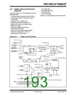
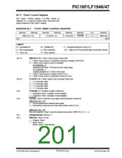
PIC16F/LF1946/47
20.7 Timer1 Interrupt
20.9 ECCP/CCP Capture/Compare Time
Base
The Timer1 register pair (TMR1H:TMR1L) increments
to FFFFh and rolls over to 0000h. When Timer1 rolls
over, the Timer1 interrupt flag bit of the PIR1 register is
set. To enable the interrupt on rollover, you must set
these bits:
The CCP modules use the TMR1H:TMR1L register
pair as the time base when operating in Capture or
Compare mode.
In Capture mode, the value in the TMR1H:TMR1L
register pair is copied into the CCPR1H:CCPR1L
register pair on a configured event.
• TMR1ON bit of the T1CON register
• TMR1IE bit of the PIE1 register
• PEIE bit of the INTCON register
• GIE bit of the INTCON register
In Compare mode, an event is triggered when the value
CCPR1H:CCPR1L register pair matches the value in
the TMR1H:TMR1L register pair. This event can be a
Special Event Trigger.
The interrupt is cleared by clearing the TMR1IF bit in
the Interrupt Service Routine.
For
more
information,
see
Section 22.0
Note:
The TMR1H:TMR1L register pair and the
TMR1IF bit should be cleared before
enabling interrupts.
“Capture/Compare/PWM Modules”.
20.10 ECCP/CCP Special Event Trigger
When any of the CCP’s are configured to trigger a spe-
cial event, the trigger will clear the TMR1H:TMR1L reg-
ister pair. This special event does not cause a Timer1
interrupt. The CCP module may still be configured to
generate a CCP interrupt.
20.8 Timer1 Operation During Sleep
Timer1 can only operate during Sleep when setup in
Asynchronous Counter mode. In this mode, an external
crystal or clock source can be used to increment the
counter. To set up the timer to wake the device:
In this mode of operation, the CCPR1H:CCPR1L
register pair becomes the period register for Timer1.
• TMR1ON bit of the T1CON register must be set
• TMR1IE bit of the PIE1 register must be set
• PEIE bit of the INTCON register must be set
• T1SYNC bit of the T1CON register must be set
Timer1 should be synchronized and FOSC/4 should be
selected as the clock source in order to utilize the Spe-
cial Event Trigger. Asynchronous operation of Timer1
can cause a Special Event Trigger to be missed.
• TMR1CS bits of the T1CON register must be
configured
In the event that a write to TMR1H or TMR1L coincides
with a Special Event Trigger from the CCP, the write will
take precedence.
• T1OSCEN bit of the T1CON register must be
configured
The device will wake-up on an overflow and execute
the next instructions. If the GIE bit of the INTCON
register is set, the device will call the Interrupt Service
Routine.
For more information, see Section 15.2.5 “Special
Event Trigger”.
Timer1 oscillator will continue to operate in Sleep
regardless of the T1SYNC bit setting.
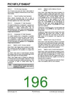
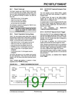
FIGURE 20-2:
TIMER1 INCREMENTING EDGE
T1CKI = 1
when TMR1
Enabled
T1CKI = 0
when TMR1
Enabled
Note 1: Arrows indicate counter increments.
2: In Counter mode, a falling edge must be registered by the counter prior to the first incrementing rising edge of the clock.
2010 Microchip Technology Inc.
Preliminary
DS41414A-page 195

 MICROCHIP [ MICROCHIP ]