PIC16F/LF1946/47
18.2 Latch Output
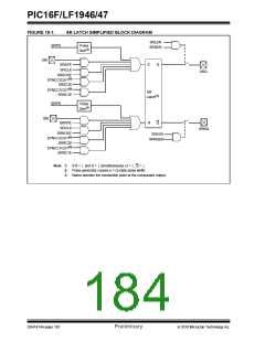
18.0 SR LATCH
The SRQEN and SRNQEN bits of the SRCON0 regis-
ter control the Q and Q latch outputs. Both of the SR
Latch outputs may be directly output to an I/O pin at the
same time.
The module consists of a single SR Latch with multiple
Set and Reset inputs as well as separate latch outputs.
The SR Latch module includes the following features:
• Programmable input selection
• SR Latch output is available externally
• Separate Q and Q outputs
The applicable TRIS bit of the corresponding port must
be cleared to enable the port pin output driver.
• Firmware Set and Reset
18.3 Effects of a Reset
The SR Latch can be used in a variety of analog appli-
cations, including oscillator circuits, one-shot circuit,
hysteretic controllers, and analog timing applications.
Upon any device Reset, the SR Latch output is not ini-
tialized to a known state. The user’s firmware is
responsible for initializing the latch output before
enabling the output pins.
18.1 Latch Operation
The latch is a Set-Reset Latch that does not depend on
a clock source. Each of the Set and Reset inputs are
active-high. The latch can be Set or Reset by:
• Software control (SRPS and SRPR bits)
• Comparator C1 output (SYNCC1OUT)
• Comparator C2 output (SYNCC2OUT)
• SRI pin
• Programmable clock (SRCLK)
The SRPS and the SRPR bits of the SRCON0 register
may be used to Set or Reset the SR Latch, respec-
tively. The latch is Reset-dominant. Therefore, if both
Set and Reset inputs are high, the latch will go to the
Reset state. Both the SRPS and SRPR bits are self
resetting which means that a single write to either of the
bits is all that is necessary to complete a latch Set or
Reset operation.
The output from Comparator C1 or C2 can be used as
the Set or Reset inputs of the SR Latch. The output of
either Comparator can be synchronized to the Timer1
clock source. See Section 17.0 “Comparator Mod-
ule” and Section 20.0 “Timer1 Module with Gate
Control” for more information.
An external source on the SRI pin can be used as the
Set or Reset inputs of the SR Latch.
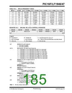
An internal clock source is available that can periodically
set or reset the SR Latch. The SRCLK<2:0> bits in the
SRCON0 register are used to select the clock source
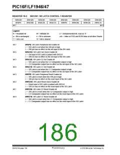
period. The SRSCKE and SRRCKE bits of the SRCON1
register enable the clock source to Set or Reset the SR
Latch, respectively.
Note:
Enabling both the Set and Reset inputs
from any one source at the same time may
result in indeterminate operation, as the
Reset dominance cannot be assured.
2010 Microchip Technology Inc.
Preliminary
DS41414A-page 181

 MICROCHIP [ MICROCHIP ]