PIC12F609/615/12HV609/615
REGISTER 4-5:
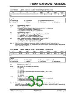
WPU: WEAK PULL-UP GPIO REGISTER
U-0
—
U-0
—
R/W-1
WPU5
R/W-1
WPU4
U-0
—
R/W-1
WPU2
R/W-1
WPU1
R/W-1
WPU0
bit 7
bit 0
Legend:
R = Readable bit
-n = Value at POR
W = Writable bit
‘1’ = Bit is set
U = Unimplemented bit, read as ‘0’
‘0’ = Bit is cleared x = Bit is unknown
bit 7-6
bit 5-4
Unimplemented: Read as ‘0’
WPU<5:4>: Weak Pull-up Control bits
1= Pull-up enabled
0= Pull-up disabled
bit 3
Unimplemented: Read as ‘0’
bit 2-0
WPU<2:0>: Weak Pull-up Control bits
1= Pull-up enabled
0= Pull-up disabled
Note 1: Global GPPU must be enabled for individual pull-ups to be enabled.
2: The weak pull-up device is automatically disabled if the pin is in Output mode (TRISIO = 0).
3: The GP3 pull-up is enabled when configured as MCLR and disabled as an I/O in the Configuration Word.
4: WPU<5:4> always reads ‘1’ in XT, HS and LP Oscillator modes.
REGISTER 4-6:
IOC: INTERRUPT-ON-CHANGE GPIO REGISTER
U-0
—
U-0
—
R/W-0
IOC5
R/W-0
IOC4
R/W-0
IOC3
R/W-0
IOC2
R/W-0
IOC1
R/W-0
IOC0
bit 7
bit 0
Legend:
R = Readable bit
-n = Value at POR
W = Writable bit
‘1’ = Bit is set
U = Unimplemented bit, read as ‘0’
‘0’ = Bit is cleared x = Bit is unknown
bit 7-6
bit 5-0
Unimplemented: Read as ‘0’
IOC<5:0>: Interrupt-on-change GPIO Control bit
1= Interrupt-on-change enabled
0= Interrupt-on-change disabled
Note 1: Global Interrupt Enable (GIE) must be enabled for individual interrupts to be recognized.
2: IOC<5:4> always reads ‘1’ in XT, HS and LP Oscillator modes.
DS41302A-page 34
Preliminary
© 2006 Microchip Technology Inc.

 MICROCHIP [ MICROCHIP ]