MCP7940M
4.1.1
RTCC REGISTER ADDRESSES
• Bit 7 is the OUT bit. This sets the logic level on the
MFP when not using this as a square wave out-
put.
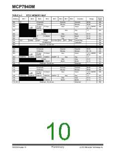
0x00h – Contains the BCD seconds and 10 seconds.
The range is 00 to 59. Bit 7 in this register is used to
start or stop the on-board crystal oscillator. Setting this
bit to a ‘1’ starts the oscillator and clearing this bit to a
‘0’ stops the on-board oscillator.
• Bit 6 is the SQWE bit. Setting this bit enables the
divided output from the crystal oscillator.
• Bits 5:4 determine which alarms are active.
- 00 – No Alarms are active
- 01 – Alarm 0 is active
0x01h – Contains the BCD minutes and 10 minutes.
The range is 00 to 59.
- 10 – Alarm 1 is active
0x02h – Contains the BCD hour in bits 3:0. Bits 5:4
contain either the 10 hour in BCD for 24-hour format or
the AM/PM indicator and the 10-hour bit for 12-hour
format. Bit 5 determines the hour format. Setting this
bit to ‘0’ enables 24-hour format, setting this bit to ‘1’
enables 12-hour format.
- 11 – Both Alarms are active
• Bit 3 is the EXTOSC enable bit. Setting this bit will
allow an external 32.768 kHz signal to drive the
RTCC registers, eliminating the need for an
external crystal.
0x03h – Contains the BCD day. The range is 1-7.
Additional bits are also used for configuration and
status.
• Bit 2:0 sets the internal divider for the 32.768 kHz
oscillator to be driven to the MFP. The duty cycle is
50%. The output is responsive to the Calibration
register. The following frequencies are available:
• Bits 3:4 are not implemented.
- 000 – 1 Hz
• Bit 5 is the OSCON bit. This is set and cleared by
hardware. If this bit is set, the oscillator is running,
if cleared, the oscillator is not running. This bit
does not indicate that the oscillator is running at
the correct frequency. The RTCC will wait 32
oscillator cycles before the bit is set. The RTCC
will wait roughly 32 clock cycles to clear this bit.
- 001 – 4.096 kHz
- 010 – 8.192 kHz
- 011 – 32.768 kHz
- 1xx enables the Cal output function. Cal
output appears on MFP if SQWE is set (64
Hz Nominal). See Section 4.2.1 “Calibra-
tion” for more details.
0x04h – Contains the BCD date and 10 date. The
range is 01-31. Bits 5:4 contain the 10’s date and bits
4:0 contain the date.
Note:
The RTCC counters will continue to
increment during the calibration.
0x05h – Contains the BCD month. Bit 4 contains the
10 month. Bit 5 is the Leap Year bit, which is set during
a leap year and is read-only.
0x08h is the Calibration register. This is an 8-bit
register that is used to add or subtract clocks from the
RTCC counter every minute. The MSB is the sign bit
and indicates if the count should be added or
subtracted. The remaining 7 bits, with each bit adding
or subtracting 2 clocks, give the user the ability to add
or subtract up to 254 clocks per minute.
0x06h – Contains the BCD year and 10 year. The
Range is 00-99.
0x07h – Is the Control register.
0x0Ah-0x0fh and 0x11-0x16h are the Alarm 0 and
Alarm 1 registers. The bits are the same as the RTCC
bits with the following differences:
Locations 0x10h and 0x17h are reserved and should
not be used to allow for future device compatibility.
0x0Dh/0x14h has additional bits for alarm configu-
ration.
• ALMxPOL: This bit specifies the level that the
MFP will drive when the alarm is triggered.
ALM2POL is a copy of ALM1POL. The default
state of the MFP when used for alarms is the
inverse of ALM1POL.
• ALMxIF: This is the Alarm Interrupt Fag. This bit is
set in hardware if the alarm was triggered. The bit
is cleared in software.
2012 Microchip Technology Inc.
Preliminary
DS22292A-page 11

 MICROCHIP [ MICROCHIP ]