MCP7940M
4.2.2
MFP
Pin 7 is a multi-function pin and supports the following
functions:
• Use of the OUT bit in the Control register for
single bit I/O
• Alarm Outputs
• FOUT mode – driven from a FOSC divider
4.2.3
CRYSTAL SPECS
The MCP7940M has been designed to operate with a
standard 32.768 kHz tuning fork crystal. The on-board
oscillator has been characterized to operate with a
crystal of maximum ESR of 70K Ohms.
Crystals with a comparable specification are also suit-
able for use with the MCP7940M.
The table below is given as design guidance and a
starting point for crystal and capacitor selection.
Crystal
Capacitance
Manufacturer
Part Number
CX1 Value
CX2 Value
Micro Crystal
Citizen
CM7V-T1A
CM200S-32.768KDZB-UT
7pF
6pF
10pF
10pF
12pF
8 pF
Please work with your crystal vendor.
It is required that the final application should be tested
with the chosen crystal and capacitor combinations
across all operating and environmental conditions.
Please also consult with the crystal specification to
observe correct handling and reflow conditions and for
information on ideal capacitor values.
EQUATION 4-1:
CX2 CX1
Cload = ----------------------------- + C stray
CX2 + CX1
The following must also be taken into consideration:
• Pin capacitance (to be included in Cx2 and Cx1)
• Stray Board Capacitance
For more information please see application note
AN1365, “RTCC Best Practices” (DS01365).
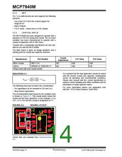
The recommended board layout for the oscillator area
is shown in Figure 4-3. This actual board shows the
crystal and the load capacitors. In this example, C2 is
CX1, C3 is CX2 and the crystal is designated as Y1.
FIGURE 4-3:
BOARD LAYOUT
Gerber files are available from www/microchip.com/
rtcc.
DS22292A-page 14
Preliminary
2012 Microchip Technology Inc.

 MICROCHIP [ MICROCHIP ]