ML4827
LEADING/TRAILING MOD. (Continued)
TYPICAL APPLICATIONS
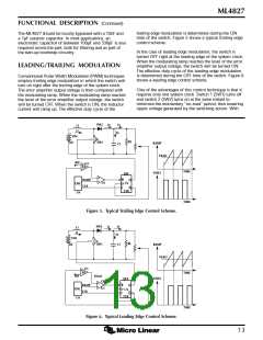
such synchronized switching, the ripple voltage of the
first stage is reduced. Calculation and evaluation have
shown that the 120Hz component of the PFC’s output
ripple voltage can be reduced by as much as 30% using
this method.
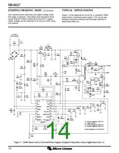
Figure 7 is the application circuit for a complete 100W
power factor corrected power supply. This circuit was
designed using the methods and topology detailed in
Application Note 33.
AC INPUT
85 TO 265VAC
F1
3.15A
C1
470nF
D1
L1
3.1mH
8A, 600V,
"FRED" Diode
Q2
IRF830
Q1
IRF840
R17
33Ω
C4
10nF
C5
100µF
R2A
357kΩ
C25
100nF
BR1
4A, 600V
D5
BYV26C
T1
R1A
D7
15V
R30
4.7kΩ
499kΩ
L2
33µH
D11
MBR2545CT
R27
39kΩ
2W
T2
R21
22Ω
R15
3Ω
12VDC
RTN
C24
1µF
R2B
357kΩ
C21
1800µF
D6
BYV26C
C20
1µF
D3
BYV26C
R28
180Ω
R24
1.2kΩ
C3
470nF
R1B
499kΩ
R14
33Ω
C30
330µF
C22
4.7µF
Q3
IRF830
C12
10µF
10kΩ
R23
1.5kΩ
D12
1N5401
R18
220Ω
9W
R7A
178kΩ
R3
75kΩ
R22
8.66kΩ
D13
1N5401
R20
1.1Ω
C23
100nF
C7
220pF
R26
10kΩ
R19
220Ω
R25
2.26kΩ
MOC
8102
R7B
178kΩ
C6
1nF
R12
27kΩ
TL431
C2
R4
470nF
13kΩ
1
16
15
14
13
12
11
10
9
IEAO
VEAO
C9
8.2nF
2
3
4
5
6
7
8
I
I
V
FB
AC
C31
1nF
R11
750kΩ
V
R8
2.37kΩ
SENSE
REF
C13
100nF
C14
1µF
C8
82nF
R5
300mΩ
1W
V
V
CC
RMS
C15
10nF
C16
1µF
SS
PFC OUT
PWM OUT
GND
C19
1µF
V
DC
D8
1N5818
RAMP 1
D10
1N5818
RAMP 2 DC I
ML4827-1
LIMIT
L1: Premier Magnetics #TSD-734
L2: 33µH, 10A DC
T1: Premier Magnetics #TSD-736
T2: Premier Magnetics #TSD-735
C17
220pF
C18
470pF
R6
41.2kΩ
R10
6.2kΩ
Premier Magnetics: (714) 362-4211
C11
10nF
Figure 7. 100W Power Factor Corrected Power Supply, Designed Using Micro Linear Application Note 33.
14

 MICRO-LINEAR [ MICRO LINEAR CORPORATION ]