KSZ8795CLX
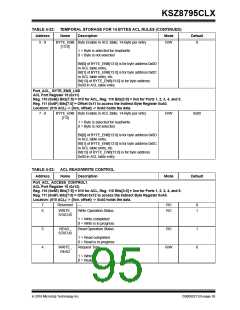
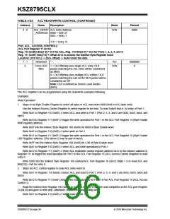
TABLE 4-23: ACL READ/WRITE CONTROL (CONTINUED)
Address
Name
Description
Mode
Default
3 - 0
ACL_ENTRY ACL Entry Address
_ADDRESS 0000 = Entry 0.
0001 = Entry 1.
R/W
0000
…..
1111 = Entry 15.
Port_ACL_ ACCESS_CONTROL2
ACL Port Register 17 (0x13)
Reg. 110 (0x6E) Bits[7:5] = 010 for ACL, Reg. 110 Bits[3:0] = 0xn for Ports 1, 2, 3, 4, and 5.
Reg. 111 (0x6F) Bits[7:0] = Offset 0x13 to access the Indirect Byte Register 0xA0.
Location: (010 ACL) -> {0xn, offset} -> 0xA0 holds the data.
7 - 1
0
Reserved
—
RO
0000000
0
Force DLR 1 = DLR filtering uses single ACL entry. DLR
R/W
Miss
packet matching the ACL entry will be considered
as MISS
0 = DLR filtering uses multiple ACL entries. DLR
packet matching the rule set for DLR packet will be
considered as HIT.
Note: DLR is defined as Device Level Redun-
dancy.
The ACL registers can be programmed using the read/write examples following:
Examples:
Read Operation
1. Steps to set Byte Enable Register to select all bytes in ACL word from 0x00-0x0d in ACL table entry:
Use the Indirect Access Control Register to select register to be read. To read Entry0 that is 1st entry of Port 1:
Write 0x41 to Register 110 (0x6E) // select ACL and write to Port 1 (Port 2, 3, 4, and 5 are 0x42, 0x43, 0x44, and
0x45)
Write 0x10 to Register 111 (0x6F) // trigger the write operation for Port 1 in the ACL Port Register 14 (Byte Enable
MSB register) address.
Write 0x3F into the Indirect Byte Register 160 (0xA0) for MSB of Byte Enable word.
Write 0x41 to Register 110 (0x6E) // select write to Port 1.
Write 0x11 to Register 111 (0x6F) // trigger the write operation for Port 1 in the ACL Port Register 15 (Byte Enable
LSB Register) address. (The above 2 may be part of burst).
Write 0xFF into the Indirect Byte Register 160 (0xA0) for LSB of Byte Enable word.
Write 0x41 to Register 110 (0x6E) // select ACL and write operations to Port 1.
Write 0x12 to Register 111 (0x6F) // Write ACL read/write control register address 0x12 to the indirect address in
Register 111 to trigger the read operation for Port 1 in the ACL Port Register 16 (ACL Access Control Register) to read
entry 0.
Write 0x00 into the Indirect Byte Register 160 (0xA0)//ACL Port Register 16 (0x12) Bit[4] = 0 to read ACL and
Bits[3:0] = 0x0 for entry 0.
2. Steps set ACL control register to read ACL entry word 0).
Write 0x51 to Register 110 (0x6E) //select ACL and read to Port 1 (Port 2, 3, 4, and 5 are 0x52, 0x53, 0x54 and
0x55).
Write 0x12 to Register 111 (0x6F) //trigger the read operation for Port 1 in the ACL Port Register 16 (ACL Access
Control 1).
Read the Indirect Byte Register 160 (0xA0) to get data (if bit[5] is set, the read completes in the ACL port Register
16 [0x12] and goes to next step. Otherwise, repeat the above polling step).
Write 0x51 to Register 110 (0x6E) // select read to Port 1.
DS00002112A-page 96
2016 Microchip Technology Inc.

 MICREL [ MICREL SEMICONDUCTOR ]