KSZ8795CLX
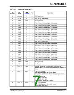
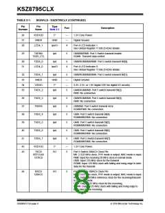
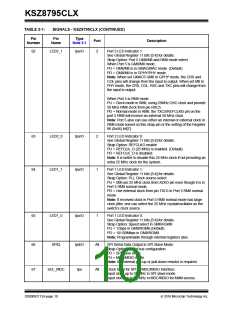
TABLE 2-1:
SIGNALS - KSZ8795CLX (CONTINUED)
Pin
Number
Pin
Name
Type
Note 2-1
Port
Description
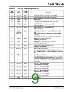
62
LED2_1
Ipu/O
2
Port 2 LED Indicator 1:
See Global Register 11 bits [5:4] for details.
Strap Option: Port 5 GMII/MII and RMII mode select
When Port 5 is GMII/MII mode:
PU = GMII/MII is in GMAC/MAC mode. (Default)
PD = GMII/MII is in GPHY/PHY mode.
Note: When set GMAC5 GMII to GPHY mode, the CRS and
COL pins will change from the input to output. When set MII to
PHY mode, the CRS, COL, RXC and TXC pins will change from
the input to output.
When Port 5 is RMII mode:
PU = Clock mode in RMII, using 25MHz OSC clock and provide
50 MHz RMII clock from pin RXC5.
PD = Normal mode in RMII, the TXC5/REFCLKI5 pin on the
port 5 RMII will receive an external 50 MHz clock
Note: Port 5 also can use either an internal or external clock in
RMII mode based on this strap pin or the setting of the Register
86 (0x56) bit[7].
63
64
LED2_0
LED1_1
Ipu/O
Ipu/O
2
1
Port 2 LED Indicator 0:
See Global Register 11 bits [5:4] for details.
Strap Option: REFCLKO enable
PU = REFCLK_O (25 MHz) is enabled. (Default)
PD = REFCLK_O is disabled.
Note: It is better to disable this 25 MHz clock if not providing an
extra 25 MHz clock for the system.
Port 1 LED Indicator 1:
See Global Register 11 bits [5:4] for details.
Strap Option: PLL Clock source select
PU = Still use 25 MHz clock from XI/XO pin even though it is in
Port 5 RMII normal mode.
PD = Use external clock from pin TXC5 in Port 5 RMII normal
mode.
Note: If received clock in Port 5 RMII normal mode has large
clock jitter, one can select the 25 MHz crystal/oscillator as the
switch’s clock source.
65
LED1_0
Ipu/O
1
Port 1 LED Indicator 0:
See Global Register 11 bits [5:4] for details.
Strap Option: Speed select in GMII/RGMII
PU = 1Gbps in GMII/RGMII.(Default)
PD = 10/100Mbps in GMII/RGMII.
Note: Programmable through internal registers also.
66
67
SPIQ
Ipd/O
Ipu
All
All
SPI Serial Data Output in SPI Slave Mode:
Strap Option: Serial bus configuration.
PD = SPI slave mode.
PU = MDC/MDIO mode.
Note: An external pull-up or pull-down resistor is required.
SCL_MDC
Clock Input for SPI or MDC/MDIO Interface:
Input clock up to 50 MHz in SPI slave mode.
Input clock up to 25 MHz in MDC/MDIO for MIIM access.
DS00002112A-page 10
2016 Microchip Technology Inc.

 MICREL [ MICREL SEMICONDUCTOR ]