KSZ8795CLX
3.1.5
10BASE-T TRANSMIT
The 10BASE-T output driver is incorporated into the 100BASE-T driver to allow transmission with the same magnetics.
They are internally wave-shaped and pre-emphasized into outputs with a typical 2.3V amplitude. The harmonic contents
are at least 27 dB below the fundamental when driven by an all-ones Manchester-encoded signal.
3.1.6
10BASE-T RECEIVE
On the receive side, input buffers and level detecting squelch circuits are employed. A differential input receiver circuit
and a PLL perform the decoding function. The Manchester-encoded data stream is separated into a clock signal and
NRZ data. A squelch circuit rejects signals with levels less than 400 mV or with short pulse widths in order to prevent
noises at the RXP or RXM input from falsely triggering the decoder. When the input exceeds the squelch limit, the PLL
locks onto the incoming signal and the KSZ8795CLX decodes a data frame. The receiver clock is maintained active
during idle periods in between data reception.
3.1.7
MDI/MDI-X AUTO CROSSOVER
To eliminate the need for crossover cables between similar devices, the KSZ8795CLX supports HP Auto-MDI/MDI-X
and IEEE 802.3u standard MDI/MDI-X auto crossover. Note that HP Auto-MDI/MDI-X is the default.
The auto-sense function detects remote transmit and receive pairs and correctly assigns transmit and receive pairs for
the KSZ8795CLX device. This feature is extremely useful when end users are unaware of cable types, and also, saves
on an additional uplink configuration connection. The auto-crossover feature can be disabled through the port control
registers, or MIIM PHY registers. The IEEE 802.3u standard MDI and MDI-X definitions are illustrated in Table 3-1.
TABLE 3-1:
MDI/MDI-X PIN DEFINITIONS
MDI
MDI-X
RJ-45 Pins
Signals
RJ-45 Pins
Signals
1
2
3
6
TD+
TD–
RD+
RD–
1
2
3
6
RD+
RD–
TD+
TD–
3.1.7.1
Straight Cable
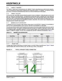
A straight cable connects an MDI device to an MDI-X device, or an MDI-X device to an MDI device. Figure 3-1 depicts
a typical straight cable connection between a NIC card (MDI) and a switch, or hub (MDI-X).
FIGURE 3-1:
TYPICAL STRAIGHT CABLE CONNECTION
DS00002112A-page 14
2016 Microchip Technology Inc.

 MICREL [ MICREL SEMICONDUCTOR ]